Using CAE Diagrams to Visualise the Arguments in Accident Reports
Chris Johnson,
Department of Computing Science, University of Glasgow, Glasgow, G12 8QQ,
Tel: +44 141 330 6053, Fax: +44 141 330 4913
johnson@dcs.gla.ac.uk, http://www.dcs.gla.ac.uk/~johnson
Accident reports help to ensure that designers and engineers learn from the mistakes of the past. Unfortunately, it can be difficult for readers to trace the increasingly complex arguments that are presented in accident reports. The integration of more and more production processes and the recognition that accident reports need to address a range of contextual and environmental issues has led to longer and longer documents. It can also be difficult for readers to locate the many different pieces of evidence that support particular arguments in an accident report. These items of information can be scattered throughout the pages of an accident report. A third problem is that readers are often forced to reconstruct complex chains of inference in order to understand the implicit arguments that are embedded within these documents. This paper has argued that the graphical structures of Conclusion, Analysis, Evidence (CAE) diagrams can be used to avoid these problems. CAE diagrams explicitly capture the relationship between evidence and lines of argument. They can also be used to capture the different viewpoints that often reflect important divisions between official accounts and eyewitness testimonies. These diagrams do not, however, directly support the subsequent development of interactive systems. We have, therefore, integrated design rationale techniques with the argumentation structures of CAE diagrams. Arguments that support or weaken particular design options can be linked to the findings that are documented in accident reports. The Australian Maritime Incident Investigation Unit’s report into a fire in the engine room aboard the Leonardo da Vinci is used as a case study in this paper.
Keywords: Accident Reports; Viewpoints; Conclusion-Analysis-Evidence Diagrams.
Accident reports document the causes of previous failures and guide the operation of future systems. However, a number of factors complicate the generation of these documents. The increasing integration of heterogeneous production processes makes it difficult to communicate the causal factors that lead to major failures. The increasing requirement to consider managerial and organisational factors is extending the scope of accident reports. Other problems stem from a cynicism that many engineers express about the veracity of accident reports (Snowdon and Johnson, 1999). Greater faith seems to be placed in the anecdotal accounts that are passed between designers and managers than in the official accounts published by investigation agencies. One reason for this is that formal reports focus on a single view of an accident. In contrast, anecdotal accounts often focus on multiple alternative explanations that may, or may not, be grounded in the available evidence. This paper, therefore, presents a simple graphical technique that can be used to represent and reason about the lines of reasoning that support particular conclusions. The intention is not to replace existing textual documents. In contrast, Conclusion, Analysis, Evidence (CAE) diagrams provide an overview for the arguments that are presented in accident reports.
1.1 The Marine Incident Investigation Unit (MIIU) Case Study
A report prepared by the Marine Incident Investigation Unit (MIIU) is used to illustrate the argument in this paper. This document describes the events leading to a fire aboard the Leonardo da Vinci, a dredger based in the Netherlands. The report also provides an overview of the crews’ response to the fire and the subsequent involvement of local shore-based fire services and of the tugs that came to support the vessel. The MIIU report summarises the incident as follows:
"On 11 June 1998, the Netherlands flag dredger Leonardo da Vinci was engaged in widening the approach channel to the Parker Point Terminal at Dampier, Western Australia. At approximately 1750, the fire alarm sounded and crew members in the engine control room saw a fire on No. 1 diesel engine. The engines were stopped, the fuel supply shutoff and the engine room battened down. A fire party attacked the seat of the fire with portable dry powder extinguishers, but as the party could not be certain the fire was fully extinguished, the Halon system was activated. Two harbour tugs provided assistance in boundary cooling until a shore fire brigade party arrived aboard. Members of the shore fire brigade party entered the engine room and, after a careful inspection, declared the fire to be fully extinguished.
The fire was caused by diesel fuel oil spraying onto the hot exhaust trunking of the engine. The source of the diesel fuel oil leak was traced to the shut-off cock to the pressure differential indicator on the No. 1 engine fuel oil filter. The bonnet of the cock had become dislodged, permitting diesel oil, under 8 bar pressure, to be sprayed upwards onto the exhaust trunking.
The fire caused extensive damage to electrical wiring and fittings, resulting in Leonardo da Vinci being out of commission for three weeks. One person was injured in the incident, receiving burns to the face and left forearm."
(MIIU, 1999).
This case study was chosen for a number of reasons. It typifies the relatively large number of incidents that do not lead to a fatality but which do have the potential to develop into major accidents (Reason, 1998). It stems from a combination of technical, managerial and operator failures that also typifies many incidents (Johnson, 1999).
A further reason for choosing this case study is that the MIIU report is covered by the Australian Navigation (Marine Casualty) Regulations. Under sub-regulation 16(3), if a report, or part of a report, relates to a person’s affairs to a material extent, the Inspector must, if it is reasonable to do so, give that person a copy of the report or the relevant part of the report. Sub-regulation 16(4) provides that such a person may provide written comments or information relating to the report. These comments are then, typically, included in the closing sections of the report. The MIIU argue that the introduction of these alternate viewpoints provides greater confidence in their findings.
1.2 Conclusion, Analysis, Evidence (CAE) Diagrams
Conclusion, analysis and evidence diagrams were specifically developed to provide a graphical overview of the argument that is presented in accident reports. They stem from the observation that many root-cause analysis techniques advocate the separation of evidence and conclusions (US DOE, 1992). This has become embodied in the format of most accident reports. The events that occurred during an accident are, typically, described in the opening chapters while the conclusions are presented at the end. This is useful because readers can form their own interpretation of events before reading the investigators’ analysis. However, such an approach can create problems when people are forced to recall important evidence that is presented many pages before the concluding chapters. Problems can also arise if readers are never explicitly told which items of evidence support a particular conclusion.
The following procedure is used during the generation of CAE diagrams:
In previous papers, we have shown how CAE diagrams can be used to reason about the internal consistency of arguments presented in accident reports (Johnson, 1999a). This paper uses CAE diagrams to chart the differences that exist between alternative accounts of the same accident. This helps to identify areas of conflict between the "official" view of an accident and eyewitness testimony. As we shall see, however, the technique is more general. It could also be applied to examine differences between, for example, the version of events advocated by a regulator and that proposed by an operating company.
2. Presenting Official Accounts of an Incident
This section shows how CAE diagrams provide an overview of the argument in the MIIU report. The case study document contains two sets of findings and so, as explained previously, this leads to two related sets of CAE diagrams. The first relates to the causes of the injury to the Technician. The second focuses on the causes of the fire in the first place.

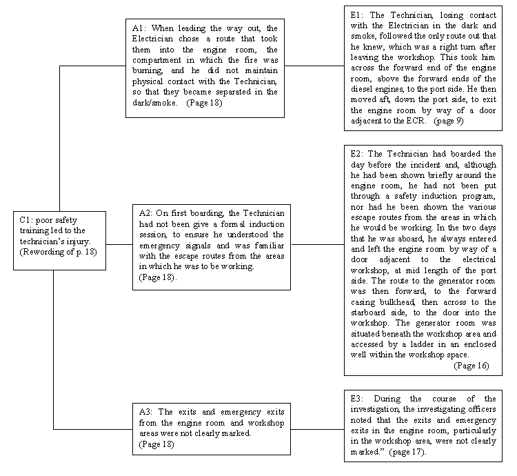
Figure 1: CAE Diagram for the Causes of the Technician’s Burns
2.1 The Causes of the Injury
The MIIU report identifies the following causes for the burns that were suffered by the technician during the fire aboard the Leonardo da Vinci:
"1. When leading the way out, the Electrician chose a route that took them into the engine room, the compartment in which the fire was burning, and he did not maintain physical contact with the Technician, so that they became separated in the dark/smoke.
2. On first boarding, the Technician had not been give a formal induction session, to ensure he understood the emergency signals and was familiar with the escape routes from the areas in which he was to be working.
3. The exits and emergency exits from the engine room and workshop areas were not clearly marked." (Page 18).
The next stage in the composition of a CAE diagram is to identify the evidence that supports each of these lines of analysis. The following paragraph reproduces sections of the MIIU report that directly address the causes of injury to the technician. As can be seen from the page numbers associated with each of these citations, the evidence and analysis of these causal factors is widely dispersed throughout the accident report. Each quotation is also separated by a wider discussion of the contextual factors that set the scene for the incident:
"The Technician, losing contact with the Electrician in the dark and smoke, followed the only route out that he knew, which was a right turn after leaving the workshop. This took him across the forward end of the engine room, above the forward ends of the diesel engines, to the port side. He then moved aft, down the port side, to exit the engine room by way of a door adjacent to the ECR. He had progressed a little less than halfway along the port side, when there was an explosion and fireball. Although struck by the blast, he was able to continue and make his exit from the engine room. He was found by a member of the crew, who took him to the galley, where other crew members administered first aid to his burnt face and left arm. He was then put aboard Sentinel, to be taken ashore." (Page 9)
"The Technician had boarded the day before the incident and, although he had been shown briefly around the engine room, he had not been put through a safety induction program, nor had he been shown the various escape routes from the areas in which he would be working. In the two days that he was aboard, he always entered and left the engine room by way of a door adjacent to the electrical workshop, at mid length of the port side. The route to the generator room was then forward, to the forward casing bulkhead, then across to the starboard side, to the door into the workshop. The generator room was situated beneath the workshop area and accessed by a ladder in an enclosed well within the workshop space." (Page 16)
"During the course of the investigation, the investigating officers noted that the exits and emergency exits in the engine room, particularly in the workshop area, were not clearly marked." (Page 17)
Figure 1 shows how these quotations can be used to construct a CAE diagram followiung the procedure outlines in Section 1.2. The previous citations also illustrate a common problem with many accident reports. They fail to accurately distinguish between inferences on the part of the investigator and those facts for which there is substantiated evidence. This distinction, typically, forms a focus for subsequent litigation. These quotations also illustrate the way in which many accident reports fail to provide any warrant for the evidence that supports their arguments. There is a section on the sources of information for the MIIU report. These are listed as follows:
"Master, officers and crew, Leonardo da Vinci
Technical representative of Jeaumont Industrie, France
Dampier Port Control Tower
Fire & Rescue Service of Western Australia
Western Australia Police Service, Karratha
The Inspector is grateful to the AMSA management for making available their two surveyors in Karratha to be appointed as Investigators to conduct the field investigation.
Portion of chart Aus 59 reproduced with permission of the Hydrographic Office, RAN".
(Page 4)
The MIIU report provides no information about the forms of analysis that were used to reach findings such as "the exits and emergency exits in the engine room… were not clearly marked". Later sections will show how this led the Chief Engineer aboard the Leonardo da Vinci to object to sections in the investigators’ account. Similarly, it is difficult to assess the reliability of assertions such as "The Technician… followed the only route out that he knew" without knowing more about the procedures that were used to validate this assertion. Readers must trust to the skills and expertise of the investigator. In this incident, the enquiry was relatively straightforward. Greater doubt can be created when, for example, human factors experts diagnose "high workload", "poor crew resource management" and "loss of situation awareness" without little or no supporting evidence (Johnson, 1999a).
Previous paragraphs have focussed on the loss of contact between the electrician and the technician as a primary causal factor in the injury. This argument takes attention away from an alternative line of analysis that centres on the loss of lighting. Little consideration is given to the technical reasons for the delay in cycling the emergency generators when the fire alarm was first raised:
"The Chief Engineer, turning from the alarm panel to the fire alarm panel, looking through the window into the engine room saw flames. He immediately telephoned the bridge and informed the Master. He then stopped the engines, which caused a brief blackout until the emergency generator cut in. He then instructed the Greaser to close the engine room flaps." (Page 8)
Figure 2 extends the previous CAE diagram to consider the role that an emergency lighting system might have played in the course of the accident. A double box is used to denote any elements of the diagram that are not direct citations for the MIIU report. As can be seen, the analysis of the lighting is marked as "supposition" because it is not directly addressed in the original document. Part of the justification for this omission may stem from the fact that smoke also hampered the technician’s escape. An emergency lighting system may not then have helped under these circumstances. This line of reasoning is also shown in Figure 2. Note that there is a dotted line between the analysis that lighting would have helped and the analysis about the smoke. As previously mentioned, this dotted line indicates that the smoke weakens any argument about the lighting system. It is important to emphasise that our primary concern is not with the particular analysis shown in Figure 2. Although we have done little more than construct arguments from the evidence that is already present in the body of the MIIU report. In contrast, we are concerned to represent the legitimate concerns or questions that arise when people read an accident report. If these concerns are to be addressed then it follows that accident investigators must explain both what did and what did NOT cause an accident (Snowdon and Johnson, 1999). Followed to its logical conclusion, this analysis might lead to accident reports that are many times their current length and which are correspondingly more expensive to produce. CAE diagrams are, therefore, intended to provide a concise graphical overview of these alternative hypotheses.
Figure 2 employs a simple reference scheme to indicate arguments and evidence that have been presented in previous CAE diagrams. A2 refers to the argument that the technician had not received any formal training on emergency procedures (see Figure 1). E3 refers to evidence that the emergency exits were not clearly marked. This is important because, as we shall see, the same item of evidence may be used to support several different arguments. Such numbering schemes also help to detect inconsistencies where, for example, a single piece of evidence may simultaneously be used to strengthen and weaken a more general argument. This numbering scheme also reduces the problems of scale that arise when mapping out the complex arguments in many accident reports. The closing sections of this paper go on to describe how tool support is also being recruited to address these problems.
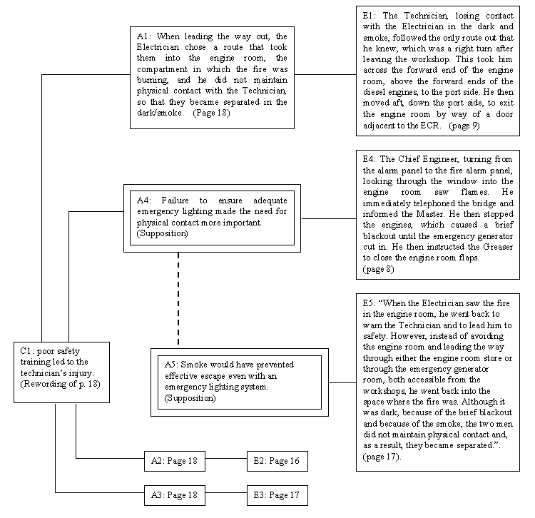
Figure 2: CAE Diagram Showing Analysis of the Emergency Lighting System
2.2 The Causes of the Fire
The injury to the technician would not, of course, have occurred if the fire had not broken out in the first place. The following list summarises the MIIU’s analysis of the causal factors that contributed to this hazard:
"1. The fire occurred when diesel oil sprayed from a shut-off cock on No. 1 engine fuel filter on to the hot exhaust trunking of No. 1 diesel engine.
2. Over an undetermined period, the spindle bonnet of the shut-off cock had vibrated loose, had unscrewed and had been blown off, permitting the escape of diesel oil under 8 bar pressure.
3. At some undetermined time, the handle of the shut-off cock had been removed, to allow access to the square head of the spindle, and had not been replaced. This action removed the locking, or keep-safe, portion of the valve.
4. Although five spare shut-off cock assemblies were held aboard, missing handles had not been replaced on two shut-off cocks, indicating a laxity towards maintenance."
(page 18).
As before, a careful reading of the body of the report helps to identify the evidence that supports these conclusions. It is then possible to map out the arguments used by the investigators. The CAE diagram shown in Figure 3 illustrates these different lines of reasoning. This diagram also illustrates the way in which a range of media can be used to support particular lines of argument. In this case, photographic evidence is used to show that the spindle bonnet of the number one shut-off cock had become detatched. Elsewhere we have shown how video material and even desktop virtual reality simulations can be used to support the on-line presentation of future accident reports (Johnson, 1999b). In contrast, this paper focuses on the arguments that are put forward by these documents rather than the media that are used to present them.
Figure 3 also illustrates how the MIIU report fails to distinguish between evidence and analysis. The first citation presents a causal analysis within the main body of the report. The second citation shows how this version of events is simply repeated within the findings of the report. This goes against the separation of evidence and argument that is a common feature of many analytical techniques (US DOE 1992):
"On investigation, the handle and spindle bonnet of the shut-off cock to No. 1 diesel filter differential pressure indicator were found to be missing. This had allowed diesel fuel, under 8 bar pressure, to spray upwards, on to the hot exhaust trunking of the engine, the heat of which had ignited the oil. The spindle was found in the bilge, beneath the engine, clean and undamaged. The body of the shut-off cock was also undamaged". (Page 12).
"The fire occurred when diesel oil sprayed from a shut-off cock on No. 1 engine fuel filter on to the hot exhaust trunking of No. 1 diesel engine". (Page 18)
Figure 3 again illustrates how the report provides little or no detail about the procedures and mechanisms that were used during the investigation. The reader is not informed about the interview techniques that were used to verify the period during which the handles for the numbers 1 and 2 diesel filters were missing. This lack of explicit warrant and the blurring of analysis and evidence can lead to the generation of further hypotheses that may or may not be supported by the findings of the investigation (Snowdon and Johnson, 1999). For instance, the MIIU report also identified further concerns that were not considered to be primary causes of the accident:
"During the investigation it also became apparent that, although it had not contributed to the fire, there had been a slight fuel oil leak from the spindle of the No. 1 diesel engine fuel filter change-over lever. This had first been recorded in the Chief Engineer’s workbook seven days before the fire, with subsequent daily entries indicating new "O" rings were required. The time required to change the "O" rings is about one hour, but the Chief Engineer did not consider the leak of sufficient significance to stop the dredging operation in order to effect the change.
All fuel oil leaks are potential hazards and should be dealt with as soon as practicable. However, it was reported that when the Chief Engineer had stopped dredging operations on an earlier occasion, but for different reasons, afterwards the dredging company reminded him that stoppages cost $10,000 an hour. Such apparent admonishments from management place pressures on ships’ personnel which can be detrimental to safety.
It is perhaps fortunate that the fire occurred immediately after the greasers had completed wiping down the engines, otherwise any accumulated oil may have ignited, extending the fire". (Page 13)
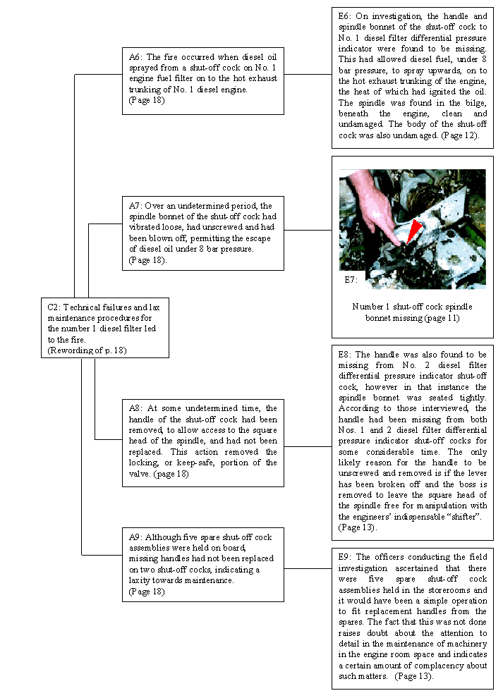
Figure 3: CAE Diagram for the Causes of the Fire
The CAE diagram in figure 3 can be extended to represent the lines of argument that are presented about both the O rings and the general maintenance procedures aboard the Leonardo da Vinci prior to the fire, see Figure 4 A10. The findings about lax maintenance procedures are also supported by the investigator’s argument that all fuel oil leeks should be dealt with as soon as practicable, A11. This analysis is linked explicitly in Figure 4 to the evidence about the Chief Engineers’ workbook, E10. This is important because the previous citations only include an implicit link between the investigator’s comments about good maintenance procedures and the delay in resolving the leaks that are noted in the Chief Engineers’ workbook. The juxtaposition of this apparent failure against the recommendation for good practice is clearly intended to make the reader infer that the Chief Engineer did not deal with the oil leak "as soon as practicable". Figure 4 makes this inference explicit by linking the implied argument to the evidence that supports it.
The evidence that is cited from the Chief Engineer’s workbook not only supports the argument about a failure to deal promptly deal with all oil leaks. This evidence is also linked to an argument about problems with the fuel filter change-over lever. This illustrates how the same observations may be used to support more than one argument. Such dependencies increase the rhetorical value of that evidence to the overall conclusions in an accident report. If it can be contradicted then two arguments may fail. CAE diagrams, therefore, indicate lines of attack that may subsequently undermine large areas of an accident report.
Figure 4 also illustrates how CAE diagrams denote evidence that weakens particular arguments that are made by the investigators. This is denoted by a dotted line between evidence and an argument. In this case, it can be argued that the implication of lax maintenance procedures, A11, is not supported by the observation that the greasers had only recently finished wiping down the engines, E12. Such intervention prevented the fire from spreading. It is important not to obscure or under-emphasise the importance of such observations because it is critical to identify those defences that worked to protect systems and their operators.
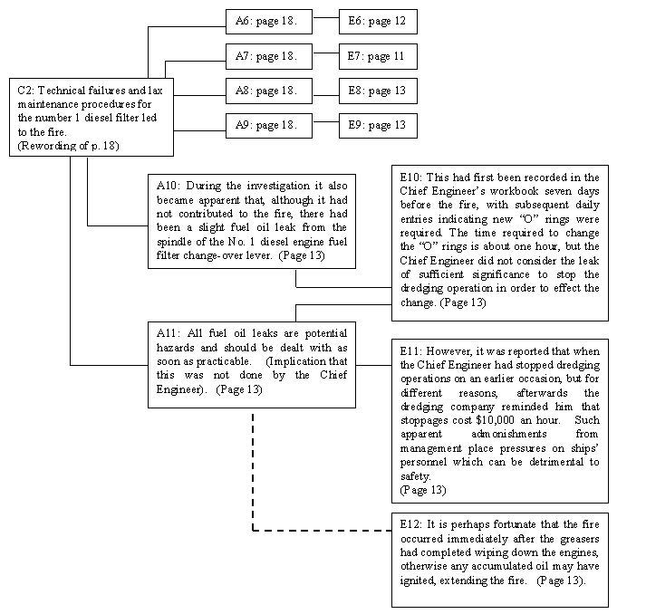
Figure 4: Representing Secondary Findings and Contradictory Evidence in an Accident Report
This section has quoted the investigators’ secondary findings in full because they widen the scope of CAE diagrams that might otherwise provide a partial view of the arguments in the MIIU report. A second justification is that these secondary findings often form the focus for litigation and dispute in the aftermath of an accident. Primary findings are, perhaps paradoxically, less prone to such rebuttal. The secondary argument shown in Figure 4 are of particular interest here because they formed the focus of debate when the Chief Engineer of the Leonardo da Vinci responded to the MIIU’s account under sub-regulation 16(4) of the Navigation (Marine Casualty) Regulations. The following sections use CAE diagrams to analyse this response to the investigators’ arguments.
3. Presenting Alternative Accounts of an Incident
As mentioned above, the Chief Engineer made a written response to the arguments that are presented in the MIIU report. The inclusion of such commentaries into the final document is an important strength of the Australian Maritime safety system. This helps to increase the reader’s confidence in the findings of such documents. The Chief Engineer’s comments were as follows:
"In particular the reference in the third paragraph of this passage to the entry in the chief Engineer’s workbook is confusing in that it is not made clear that this reference deals with a separate assembly to the one from which the fire was caused. At the time that the entry in the workbook was initiated there was no indication that a problem might be developing in relation to the separate differential pressure indicator shut off cock assembly.
The implication in this paragraph is that if the ‘O’ rings referred to had been changed, the fire would not have occurred. But, (as has been pointed out immediately above), these ‘O’ rings were part of a different assembly which was not the cause of the fire. It was not known that a problem was about to develop with the differential pressure indicator shut off cock assembly. To infer that the replacement of the ‘O’ rings, referred to above, in the separate assembly may have led to work on the differential pressure indicator shut off cock assembly is purely speculative. It was not known that a problem was about to develop in this assembly." (Page 19)
Both the investigator’s analysis and the Chief Engineer’s response are critical for our understanding of this incident. In particular, they provide valuable insights into the reasons why the preconditions, or initial causes, for the incident were not detected before the fire started. The official report suggests that the causes of the fire, i.e. the loose Number 1 shut-off cock spindle bonnet, might have been discovered if the crew had replaced the ‘O’ rings that were known to need replacing. However, this implication is contradicted in the Chief Engineer’s statement. He argues that it would not have led to the detection of this primary cause of the accident because the ‘O’ rings are part of a different assembly.
Figure 5 illustrates how this dispute over the significance of the oil leak from the spindle of the Number 1 engine fuel filter can be represented within a CAE diagram. The graphical notation provides an overview of arguments that rebut the official findings of an accident investigation. These opposing arguments, A12 and A13, are labelled by both their page number within the MIIU report and their source, in this case the Chief Engineer. As before, we have used reference numbers to indicate arguments and evidence that are presented in previous diagrams.
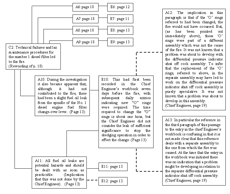
Figure 5: Using CAE Diagrams to Represent Alternative Views of an Accident
Figure 5 only captures a small part of the Chief Engineer’s comments on the MIIU report. His testimony continues:
"There is reference to the standard of maintenance in the engine room and speculation that "complacency" existed with respect to maintenance. This viewpoint is put forward on the basis of spare parts held for the assembly that caused the fire. But, as has already been pointed out in 1 above, it was not known that a problem existed or was developing with this assembly. Consequently the connection between the number of available spare parts for this assembly and alleged complacency in relation to maintenance has not been established. There is no connection." (Page 20)
The Chief Engineer argues that the presence of replacement parts for the shut-off cock need not imply that lax maintenance was a central cause of the fire. Figure 6 shows how this objection, A14, relates to the analysis, A9, in the official report.
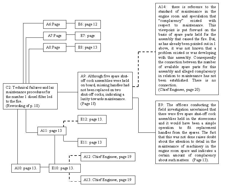 Figure 6: Chief Engineer’s Objection to Evidence of Lax Maintenance
Figures 5 and 6 raise a number of wider issues. In figure 5, the objection is denoted as two arguments, A12 and A13, that attack the evidence, E10, about records in the Chief Engineer’s workbook. However, in Figure 6, the Chief Engineer’s criticism, A14, is aimed at the analysis or interpretation of the spare shut-off assemblies. This clearly reflects a subjective judgement on the part of the analyst. There is no predefined algorithm that can be used to categorise the natural language comments of eyewitnesses into objections against particular lines of analysis or evidence. There are a number of heuristics or rules of thumb that can be applied. Such objections should be linked to items of evidence if they attack the validity of that evidence, as shown in Figure 5. Otherwise, objections should be linked to the investigator’s analysis, as in Figure 6. However, experience in drafting CAE diagrams has shown that things are seldom so clear cut. In Figure 5, argument A13 does not directly contradict the evidence about the workbook entries. It does, however, attack the interpretation of that evidence as well as the subsequent implication that is based upon this interpretation. The Chief Engineer accepts that the workbook entry about the ‘O’ rings does exist. However, he denies that this evidence has any baring on the possible detection of the spindle bonnet problem. Therefore, the objection could have been linked to either the evidence of the ‘O’ rings problem, E10, or the subsequent analysis, A11 and A10. It is important to stress that this detailed level of analysis indicates an important benefit of CAE diagrams. They provide a graphical overview that can be used to represent and reason about the full implications of the objections and criticisms that are often raised during the drafting of an accident report.
The Chief Engineer also addressed the personal injury to the technician. In particular, he criticised the MIIU’s conclusions that the technician did not receive adequate training during the short period that they were working on the vessel and that poor signing should have been identified as a problem during routine inspections on the Leondardo da Vinci:
"With respect to the conclusion that the technician who experienced a personal injury as a result of the fire was not given a "formal induction session", the only comment I can make is that I am aware that this individual was shown around the machinery spaces. He was given a "familiarisation" session. Also, I would point out that the "exits and emergency exits from the engine room and work shop area that were not clearly marked" could and should have been picked up when the vessel was initially inspected by AMSA." (Page 12)
As before, these objections can be integrated into CAE diagrams of the arguments in the official report. Figure 7 splits the previous paragraph into two lines of argument. The analysis labelled A15 focuses on the lack of a formal induction course. A16 focuses on the failure of previous AMSA inspections to identify the poor signage. In the former case, this is interpreted as an objection to the evidence that the technician had not been put through a safety induction programme on the Leonardo da Vinci. In the later case, this is shown as an objection to the analysis that the exits and emergency exits were not clearly signed. The official report argues that this is the case on the basis of the technician’s failure to find an exit that avoided the seat of the fire. However, the Chief Engineer argues that independent inspectors passed the signs.
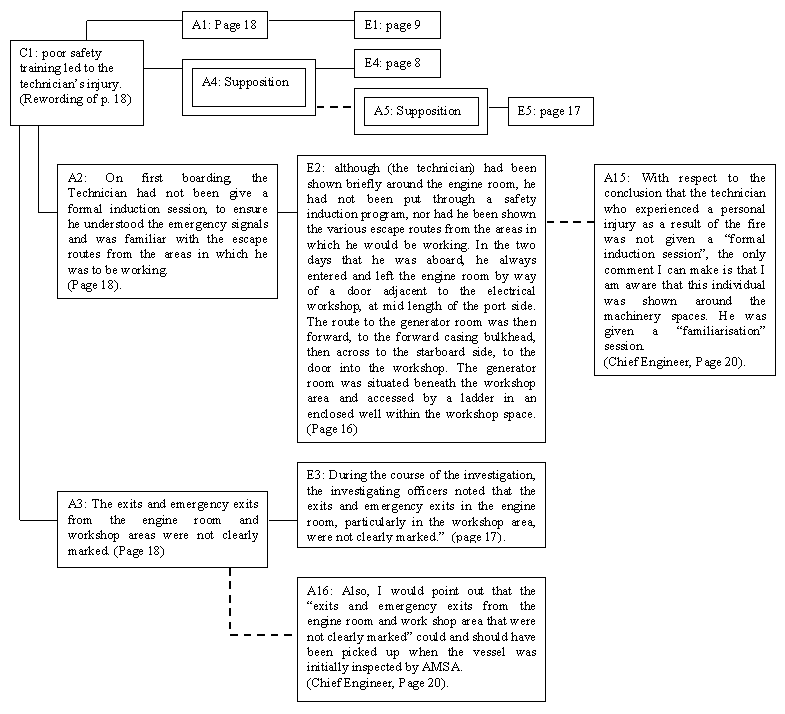
Figure 7: Chief Engineer’s Objection to the Official Causes of the Technician’s Injuries
Previous sections have shown how CAE diagrams represent the conclusions, analysis and evidence that are presented in accident reports. They provide an overview of the complex arguments that are constructed in many of these documents. The same diagrams can also be used to reason about potential weaknesses in an argument, for example, where several lines of analysis depend on the same item of evidence. We have also shown how these diagrams can be extended to represent the opposing arguments that are often made by eyewitnesses in the aftermath of an incident. They provide a graphical representation of the multiple viewpoints that can help a reader’s understanding of an incident or accident (Johnson 1999, Reason 1998). However, all of this is of limited benefit if analysts cannot apply CAE diagrams to support the subsequent design and operation of safety-critical systems.
4. Presenting the Justification for Design Decisions
This section explains how techniques from design rationale (Buckingham Shum, 1995) can be used in conjunction with CAE diagrams to provide a link between the analytical techniques of accident investigations and constructive design.
4.1 Design Rationale
Design rationale notations provide a graphical overview of the arguments that support particular development decisions (Moran and Carrol, 1995). For instance, the Questions, Options and Criteria (QOC) notation was originally developed to support a range of engineering decision-making activities within the Rank Xerox Corporation. Its syntax is almost identical to that used in CAE diagrams; CAE diagrams were originally developed from the QOC notation. The first step in producing a QOC diagram is to identify the key development questions. These are then linked to the options that answer those questions. Finally the criteria that support or weaken options are added to the diagram. As in CAE diagrams, a broken lines is used to denote negative criteria. Figure 8 illustrates how the QOC (Questions Options and Criteria) notation can represent the design options that were considered to improve situation awareness amongst crews on the Heath Reef in Australia (Johnson, 1999a). The first option is to force all ships to notify their position to an existing monitoring system. This is supported by the criteria that it would provide an external means of ensuring that crews comply with regulations. The Reefrep system could monitor and log the reporting behaviour of each vessel. The development of such a system is not supported by the affect that it would have upon crew workload. The second design option is to use crew training procedures as a means of ensuring adequate levels of situation awareness. This is not supported by the possibility of performing external checks.

Figure 8: QOC diagram showing design options for improved situation awareness.
Ideally, we would like to produce a similar diagram for the various recommendations that were presented in the MIIU report. This is usually a trivial task; most accident reports list their findings for the future development and operation of similar systems. However, the MIIU case study is atypical. It does not explicitly identify any recommendations that might be derived from the analysis of this incident. Instead, the reader is forced to infer the lessons that might be drawn for the future improvement of these systems. Figure 9 presents some of these inferences.
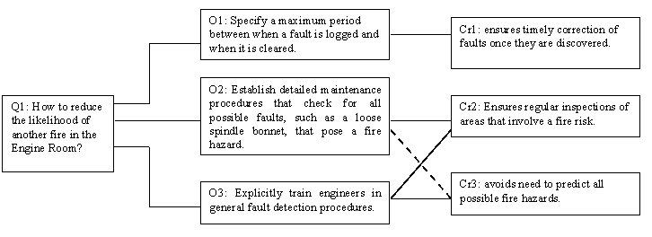
Figure 9: QOC diagram showing design options for fire avoidance.
As mentioned, figure 9 is derived from a subjective analysis of the MIIU report. The question of how to reduce the likelihood of an engine room fire can be addressed by three possible design options. The first option is to specify a maximum period within which any logged fault must be resolved. This is supported by the argument that it will ensure the timely correction of faults once they are discovered. The second option is to establish a detailed maintenance regime for all possible fire hazards. This is supported by the criteria that it will involve a regular inspection of all known fire hazards but is weakened by the criteria that it requires engineers to accurately predict all possible fire hazards. The final option relies upon training improvements to help staff detect faults. This avoids the need for engineers to identify all possible fire hazards and then create explicit inspection procedures as suggested by option two. It is important to note, however, that QOC’s do not enforce an exclusive selection between competing alternative. It would be perfectly possible to exploit all three of the options identified in Figure 9.
Figure 9 omits one recommendation that did emerge from the investigation but which was not directly addressed within the MIIU report. This is unfortunate because the recommendation has considerable implications for the readers’ view of this accident:
"A possible contribution to the fire was the potential design fault that has now been rectified as a bonnet has been placed over the "duplex fuel filtration area" to eliminate the potential of diesel fuel being sprayed upwards onto a hot exhaust." (Page 20)
The Chief Engineer’s testimony contains the observation that the shut-off cock was re-designed in the aftermath of the fire. It might have been better to include this information within the main body of the report. The fact that this accident might have been avoided through improved design, rather than through increasingly elaborate training and maintenance procedures, introduces a further dimension to the development options shown in Figure 9.
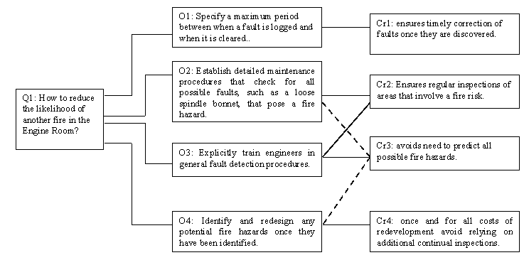
Figure 10: Design options for fire avoidance revised after Chief Engineer’s testimony.
A major limitation with the previous diagram is that it provides little or no indication of the status or source of the options and criteria that are represented. In other words, we have no means of assessing whether or not it is possible to identify all possible fire hazards (Option 2). Nor does the previous diagram show how a particular option will guarantee that faults, which are detected, can be resolved within some maximum time period (Criterion 1). Such problems can be avoided by integrating design rationale techniques, such as the QOC notation shown in Figure 10, with the findings of accidents and incident investigations.
4.2 Using Accidents to Provide Contextual Support For Development Decisions
Figure 10 integrates CAE and QOC diagrams for the fire aboard the Leonardo da Vinci. The CAE diagram represents the MIIU's finding that technical failure and lax maintenance procedures led to the fire. A link is then drawn to the QOC diagram to show that this finding justifies designers in considering how to reduce the likelihood of fire within the engine room. It is important not to underestimate the benefits that such links provide. By linking development documents directly to the products of accident investigations, it is possible to ensure that designers base their subsequent development decisions at least partly upon those problems that have arisen with previous applications.
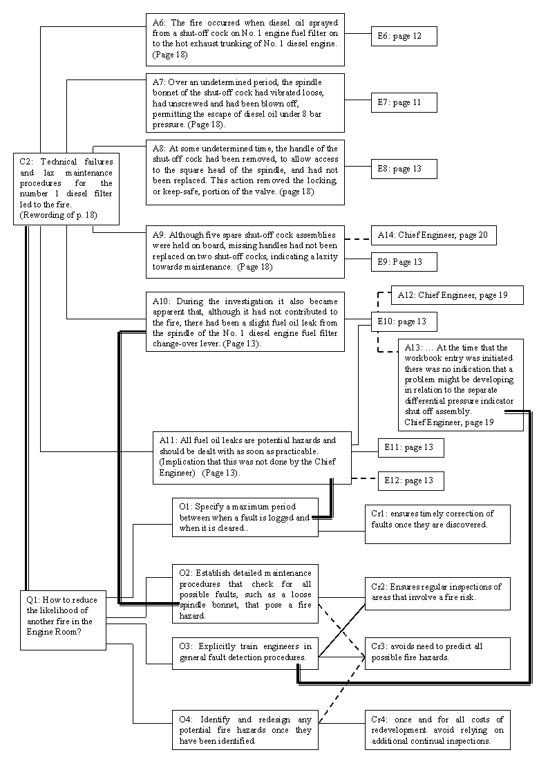
Figure 11: Using Previous Accidents to Justify Asking the Questions in QOC Diagrams.
Further links are shown between the QOC and the CAE diagrams. For example, the option of specifying a maximum time limit for fault resolution, O1, is supported by the MIIU argument, A11, that all leaks are potential hazards and must be dealt with as soon as practicable. The option of establishing detailed maintenance procedures to detect all possible faults, O2, is supported by the argument that not only had the shut-off cock spindle bonnet worked loose but there were other problems with the spindle of the Number 1 change-over lever, A10. Finally, the option not to attempt to predict all possible faults, O3, is supported by the Chief Engineer’s observation that the inspection of a particular fault, such as the change-over lever problem, might miss other faults, such as the one that developed in the shut-off spindle bonnet, A13.
It is important to emphasise that we are not primarily concerned with the particular causes of the fire aboard the Leonardo da Vinci. In contrast, we are concerned to demonstrate that designers can use past accidents to inform subsequent development. It is also important to note that the previous diagram also indicates the various lines of argument for and against particular design options. By combining the CAE and QOC diagrams, it is possible to see that more information is needed to explain the re-design of the spindle bonnet. It also raises questions about why the reasons for this design failure were not presented within the MIIU report when operator error and maintenance failure were considered in detail.
5. Further Work
A number of areas for future work have been identified.
5.1 Subjectivity in the analysis
Our use of CAE diagrams has much in common with Peter Ladkin’s work on Why-Because Graphs (Ladkin, Gerdsmeier and Loer, 1997). Both approaches have, in the past, rewritten the prose that is presented in accident reports before annotating diagrams. This improves the clarity of the exposition and helps to reveal the argument in the accident report. We could have rewritten sections of the MIIU report so that each paragraph is easily classified as a Conclusion, a line of Analysis or an item of Evidence. There is, however, a danger that this rewording may lose the initial meaning of the investigator’s prose. We have, therefore, rejected this approach. Verbatim citations have been taken from the MIIU report so that they can be directly integrated into CAE diagrams.
The use of direct quotations raises a number of further problems. In particular, the natural language in an accident report cannot easily be reclassified into the simple distinctions supported by CAE diagrams. Previous sections have shown that particular paragraphs in the MIIU document present evidence, analysis and conclusions side by side. This rhetorical technique carries its own dangers; it can be difficult to distinguish between suppositions and facts or inferences. It is possible to represent the more fine-grained argumentation structures that are used in natural language. A number of detailed diagrammatic techniques have been used to represent and reason about the structure of argument in other domains. The gIBIS approach is an example of such a technique (Conklin and Begeman, 1989). However, it can be extremely difficult for readers to recall the many different types of nodes that are denoted in these diagrams (Moran and Carrol, 1995). Further work is needed to determine whether the costs of introducing additional syntactic features are offset by the greater precision in representing the arguments that are presented in accident reports. Similarly, more work needs to be conducted to determine whether it is appropriate to constrain the semantics of the links between CAE and QOC diagrams. Our initial development of this technique has exploited informal guidelines about the precise nature of these connections. However, it is likely that these guidelines may have to be codified if the approach is to be used by teams of accident investigators and systems designers.
5.2 Tool support
CAE diagrams were developed to provide a graphical overview of the increasingly complex arguments that are presented in accident reports. The increasing integration of production processes and the recognition that accident reports need to address a range of contextual and environmental issues has led to longer and longer documents. However, the integration of CAE diagrams and design rationale, shown in Figure 11, raises a number of questions about the scalability of our approach. The MIIU report was only twenty-one pages long. Even so, the complexity of the argument makes it difficult to represent on a single page of A4 paper. Correspondingly, we might expect that many more pages would be required to capture the argument in the 488 pages of the Cullen report into the Piper Alpha fire. The length of such documents not only presents a challenge to our research but also helps to justify it. It is impossible for most readers to retain a coherent overview of the argumentation in such reports. The only solution to the scalability problems that frustrate the application of CAE diagrams would seem to be the provision of tool support. We are aware that the proliferation of hypertext links can lead to a complex tangle, which frustrates navigation and interpretation by interface designers and regulatory authorities.
6.Conclusion and Further Work
Accident reports help to ensure that designers and engineers learn from the mistakes of the past. Unfortunately, it can be difficult for readers to locate the many different pieces of evidence that support particular arguments about the causes of an accident or incident. These items of information can be scattered throughout the pages of an accident report. A second problem is that readers are often forced to reconstruct complex chains of inference in order to understand the implicit arguments that are embedded within these documents.
This paper has argued that the graphical structures of Conclusion, Analysis, Evidence (CAE) diagrams avoid these problems. CAE diagrams explicitly capture relationships between evidence and analysis. They also provide a graphical overview of the competing lines of argument that might contradict particular interpretations of human ‘error’ and systems ‘failure’. They can also be used to capture the different viewpoints that reflect important disagreements between official accounts and eyewitness testimonies. However, these diagrams do not directly support subsequent development. We have, therefore, integrated design rationale techniques with the argumentation structures of CAE diagrams. This offers a number of benefits. For example, arguments that support or weaken particular design options can be linked to the findings that are documented in accident reports.
The Australian Maritime Incident Investigation Unit’s report into a fire in the engine room aboard the Leonardo da Vinci has been used to illustrate this paper. This case study has revealed the strengths of CAE diagrams, for example in providing an overview of the arguments that were presented. It has also helped to identify weaknesses. For example, the rhetorical techniques used in the report often made it difficult to identify the evidence that supported particular lines of argument. However, we were able to show that CAE diagrams can capture the alternate views that were presented in the Chief Engineer’s submission under clauses 16(3-4) of the Australian Navigation (Marine Casualty) Regulations. We also identified an important omission in the MIIU document. The official report failed to mention the design improvements that were made to the spindle bonnet, which caused the fire.
Acknowledgements
Thanks are due to the members of the Glasgow Accident Analysis Group and the Glasgow Interactive Systems group who provided valuable help and encouragement with this research. In particular, I would like to thank the Australian Marine Incident Investigation Unit for their openness in providing access to the accident report that is used to illustrate this paper. I would also like to commend the innovative way in which sub-regulations 16(3-4) of the Australian Navigation (Marine Casualty) Regulations helps readers to understand the broader context of accidents such as the fire that is considered in this paper.
References
S. Buckingham Shum, Analysing The Usability Of A Design Rationale Notation. In T.P. Moran and J.M. Carroll (eds.), Design Rationale Concepts, Techniques And Use, Lawrence Erlbaum, Hillsdale, New Jersey, United States of America, 1995.
J. Conklin and M.L. Begeman , gIBIS: A Tool For All Reasons, Journal Of The American Society For Information Science, 200-213, May, 1989.
US Department of Energy, Root cause analysis guidance document. DOE-NE-STD-1004-92. Office of Nuclear Energy, Washington DC, 1992.
C.W. Johnson, Visualising the Relationship between Human Error and Organisational Failure. In J. Dixon (ed.) Proceedings of the 17th International Systems Safety Conference, The Systems Safety Society, Unionville, Virginia, United States of America, 101-110, 1999.
C.W. Johnson, A First Step Towards the Integration of Accident Reports and Constructive Design Documents. In M. Felici, K. Kanoun and A. Pasquini (eds.), Computer Safety, Reliability and Security: Proceedings of 18th International Conference SAFECOMP'99, 286-296, Springer Verlag, 1999a.
C.W. Johnson, Improving the Presentation of Accident Reports over the World Wide Web. In J. Dixon (ed.) Proceedings of the 17th International Systems Safety Conference, The Systems Safety Society, Unionville, Virginia, United States of America, 396-405, 1999b.
P. Ladkin, T. Gerdsmeier and K. Loer, Analysing the Cali Accident With Why?...Because Graphs. In C.W. Johnson and N. Leveson (eds), Proceedings of Human Error and Systems Development, Glasgow Accident Analysis Group, Technical Report GAAG-TR-97-2, Glasgow, 1997.
Maritime Incident Investigation Unit, Investigation into a Fire in the Engine Room Aboard the Netherlands Dredger – Leonardo da Vinci off the Port of Dampier, WA, on 11 June 1998. Report 131, ISBN 0 642 20018 1, Department of Transport and Regional Development, Canberra, Australia, 1999.
T.P. Moran and J.M. Carroll (eds.), Design Rationale Concepts, Techniques And Use, Lawrence Erlbaum, Hillsdale, New Jersey, United States of America, 1995.
J. Reason, Managing the Risks of Organisational Accidents, Ashgate, Aldershot, 1998.
P. Snowdon and C.W. Johnson, Results of a Preliminary Survey into the Usability of Accident and Incident Reports. In J. Noyes and M. Bransby (eds.), People in Control, 258-262, The Institute of Electrical Engineers, Savoy Place, London, United Kingdom, 1999.