In general we need a more systematic method of designing a logic circuit which computes a given logic function. We will again use majority voting as an example, but later on we will use the same techniques to design circuits for functions which are more relevant to computer design - for example, addition.
This time we will begin with the truth table for the majority voting function; it is a convenient way of specifying the function precisely.
|
| x = 0 and y = 1 and z = 1 |
| or |
| x = 1 and y = 0 and z = 1 |
| or |
| x = 1 and y = 1 and z = 0 |
| or |
| x = 1 and y = 1 and z = 1 |
| [`x] = 1 and y = 1 and z = 1 |
| or |
| x = 1 and [`y] = 1 and z = 1 |
| or |
| x = 1 and y = 1 and [`z] = 1 |
| or |
| x = 1 and y = 1 and z = 1 |
| [`x]yz = 1 |
| or |
| x[`y]z = 1 |
| or |
| xy[`z] = 1 |
| or |
| xyz = 1 |
|
If we are working with n variables (inputs to a logical function), it's clear that there are 2n possible minterms - each minterm involves all n variables, and each variable is either negated ([`x]) or not negated (just x).
Each minterm corresponds to one row of the truth table, i.e. to one combination of values (0 or 1) of the variables. The correspondence is straightforward: the minterm corresponds to the row in which the negated variables have value 0 and the non-negated variables have value 1.
For example, the minterm x[`y] [`z] corresponds to the row in which x = 1, y = 0 and z = 0.
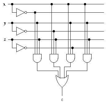
The formula for r consists of the minterms corresponding to the truth table rows in which r = 1, OR ed together.
In this way, any truth table can be converted into a circuit with the same general structure as the one for majority voting. A truth table with m inputs and n rows with output value 1, generates a formula with n minterms involving m variables. The corresponding circuit consists of m NOT gates, n m-input AND gates, and one n-input OR gate. Depending on the hardware available, the multi-input gates can either be used directly or replaced by combinations of 2-input gates.
Notice that the circuit we have produced for the majority voting function is considerably more complex than the original circuit. We will have more to say about this later.
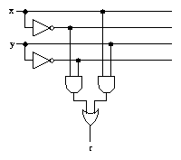
For two variables there are 4 possible minterms, which correspond to the rows of the truth table as follows:
|
|
(More generally, the parity of a number is odd or even.)
The parity function for a 3 bit word xyz is defined by the following truth table, which also shows the minterm for each row.
|
|
Suppose that each memory location stores an 8 bit word. A memory device with parity checking would actually store 9 bits per word, where the 9th bit is the parity of the original 8 bit word. The parity bit is calculated when a value is stored in memory.
When a word is read from memory, its parity is calculated and compared with the parity bit. If a single bit within the word has been corrupted (i.e. had its value changed), for example as the result of an electrical fluctuation, a cosmic ray strike, or whatever, then the parity of the word no longer matches the parity bit, and an error can be reported.
The same idea can be used when transmitting data over a network.
Parity checking can only detect single bit errors, but it might be acceptable to assume that the probability of two errors in a single word is very small.
Parity checking cannot correct errors, because it is not possible to work out which bit was corrupted. In a networking application, the corrupted word would be retransmitted.
In applications where errors are more likely and must be corrected (for example, radio transmissions from spacecraft), various error correcting codes are available. Note that error correcting requires redundancy, so the use of error correcting codes always reduces the data transmission rate.
|
|
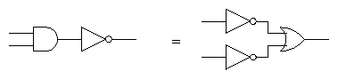
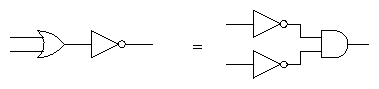
In circuits: