Simplifying Circuits
Simplifying Circuits
Recall the majority voting circuit. We have two different logical
expressions:
and
|
r = |
x
|
yz + x |
y
|
z + xy |
z
|
+ xyz |
|
The first was derived by thinking about the meaning of majority
voting, while the second was derived systematically from a truth
table.
The two expressions are equivalent, in the sense that they represent
the same function and have the same truth table. However, the first is
obviously much simpler than the second, and leads to a circuit with
fewer components.
Clearly our method of deriving a logical expression from a truth table
does not yield the simplest possible expression. We would like a
systematic way of simplifying logical expressions.
The aim of the next lecture is to present such a systematic technique. But
first, consider the following non-systematic approach.
Using Boolean Algebra
Using the algebraic laws of the logical operators (the laws of
Boolean Algebra, as it is known) we can rewrite r as follows.
|
|
|
|
|
x
|
yz + x |
y
|
z + xy |
z
|
+ xyz |
| |
|
|
|
x
|
yz + x |
y
|
z + xy |
z
|
+ xyz + xyz + xyz |
| |
|
|
|
x
|
yz + xyz + x |
y
|
z + xyz + xy |
z
|
+ xyz |
| |
|
|
yz |
x
|
+ yzx + xz |
y
|
+ xzy + xy |
z
|
+ xyz |
| |
|
|
yz( |
x
|
+ x) + xz( |
y
|
+ y) + xy( |
z
|
+ z) |
| |
|
| |
|
|
|
This calculation shows that the two definitions of r are equivalent,
but we can't consider it a systematic technique - without knowing
what we are aiming for, it is not obvious which algebraic
manipulations to apply.
However, after the first step (the introduction of the extra xyz
terms) all we have done is look for occurrences of the pattern
xy[`z] + xyz, which can be factorised as xy([`z] + z) and
simplified to xy.
The result is a sum of products of two variables, rather than three.
Karnaugh Maps
A Karnaugh map, or K-map, is an alternative representation of a truth
table, which makes it easy to spot when expressions of the form
[`x] + x can be eliminated.
As an example, consider the function r = xy + y, which has the following
truth table.
We can lay out the truth table as a 2x2 grid:
This grid is the Karnaugh map for r. Each square corresponds to one
of the four combinations of values of x and y. The values of x
and y are shown at the left hand side and along the top. The rows
are labelled with [`x] and x, and the columns with [`y] and
y, to show which axis corresponds to which variable and also to
indicate which minterm corresponds to which square in the grid. For
example, the bottom left square corresponds to the minterm x[`y].
From the Karnaugh map, we can write down a formula for r by
OR -ing together the minterms corresponding to the squares which
contain 1. In this case, we obtain
This can be factorised as
and therefore simplifies to
This is just what we did for the majority voting function, but now
notice that the presence of [`x] + x in the formula has a visual
interpretation in the K-map: there are two adjacent 1s in the y
column, covering both the x and [`x] squares.
Exercise Draw a K-map for the function
Simplification with K-Maps
The K-map for the function
is as follows:
Picking out the 3 minterms with value 1 shows that
Making use of the horizontal block of two 1s gives
the original definition.
Making use of the vertical block of two 1s instead gives
The simplest expression is obtained by using both the horizontal and
vertical blocks:
and indeed the K-map obviously corresponds to the truth table for OR .
2 Input K Map Exercise
The following exercise will give you some practice in simplifying 2 input K Maps to Minterms.
This exercise can be found at the following page : Two Input K Map Exercise
K-maps for 3 Variables
The Karnaugh map for a function of 3 variables consists of a grid of 8
squares. Here is the K-map for the majority voting function.
The 0s and 1s around the edges have been omitted; remember that a
negated label corresponds to 0 and a non-negated label to 1.
Notice that the negated ys appear in a different pattern from the
negated zs; this means that again each square corresponds to one of the 8
minterms.
We can now see three overlapping rectangles in the K-map,
corresponding to yz, xy and xz. OR -ing these expressions
together gives the simplified formula for majority voting:
It is essential to label the rows and columns correctly, otherwise the
technique of finding overlapping rectangles does not work. It must be
the case that any two adjacent squares (including ``wrapping around''
from left to right) have labels which differ by
negation of exactly one variable. There are several labelling
schemes which have this property, but for safety you should
memorise the labelling which is used in the lecture notes.
Another Example
We will use a Karnaugh map to minimise the formula
|
x |
z
|
+ |
x
|
y |
z
|
+ yz + x |
y
|
z. |
|
First we fill in the K-map. The terms x[`z] and yz correspond to
2x1 rectangles, and the other two terms are just squares.
There are now various ways of rewriting the formula by spotting
rectangles of 1s in the K-map. Using the three horizontal 2x1
rectangles gives
The central 2x2 square corresponds simply to y, as it covers all the
squares labelled y.
Using the 2x2 square and the two remaining squares gives
The 4x1 rectangle in the bottom row corresponds to x. Combining this
with the 2x1 rectangle in the top row gives
Finally, notice that the central 2x2 square (corresponding to y) and
the bottom row (corresponding to x) cover all the 1s between them
(and overlap slightly, but this does not matter). Therefore we obtain
the simplest form of the original formula:
Exercise In the same way, minimize the expression
Notice that the leftmost column and the rightmost column of a
3-variable Karnaugh map should be considered adjacent, as they are
both labelled [`y].
3 Input K Map Exercise
The following exercise will give you some practice in simplifying 3 input K Maps to Minterms.
This exercise can be found at the following page : Three Input K Map Exercise
K-maps for 4 Variables
A Karnaugh map for a function of 4 variables x, y, z, w uses
the following grid.
Just as in the case of 3 variable maps, the leftmost and rightmost
columns are considered to be adjacent. In addition, the top and bottom
rows are adjacent because they are both labelled [`w].
Karnaugh maps can be constructed for functions of 5 or more
variables. For example, a K-map for 5 variables consists of two copies
of the 4-variable K-map, one labelled v and the other labelled
[`v]. However, beyond 4 variables K-maps become less useful
because it is more difficult to identify rectangles.
4 Input K Map Exercise
A final K Map exercise will give you some practice in simplifying 4 input K Maps to Minterms.
This exercise can be found at the following page : Four Input K Map Exercise
Example: Gray Code
Gray code is an alternative binary counting sequence. The Gray code
sequence for 3 bits is as follows:
At each step, exactly one bit is changed, and it is the rightmost bit
such that a change produces a word which has not already
occurred.
Exercise: use this rule to work out the Gray code
sequence for other numbers of bits.
We will design a circuit to calculate the next 3 bit Gray code. Given
a 3 bit input xyz, the 3 bit output x'y'z' will be the word which
follows xyz in the Gray code sequence. We will consider the sequence
to be cyclic, so that after 100 we return to 000.
Here is a truth table (really, 3 truth tables combined) showing x',
y' and z' as functions of x, y and z.
For each of x', y', z' we can draw a Karnaugh map, in order to
find a minimised formula.
Karnaugh map for x':
Karnaugh map for y':
Karnaugh map for z':
In each case, the 1s can be covered by two 1×2 rectangles,
giving the following formulae.
Notice that the expression y[`z] occurs twice, so we can reduce
the size of the circuit by only calculating it once.
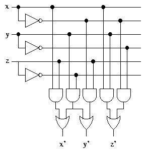
Also notice that z' = [`(x �y)], which means that if XOR
gates are available then the circuit can be simplified further.
Traffic Lights
Suppose we want to design a controller for a set of traffic
lights. British traffic lights have three lights, coloured red, amber
and green.
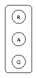
There are four possible combinations of the lights:
- Red
- Red and Amber
- Green
- Amber
The lights cycle repeatedly through these combinations in this order,
with appropriate delays.
The first step in designing the traffic light controller is to design
a circuit which has an input representing which of the four
combinations is required, and generates an output (1 or 0,
representing on or off) for each of the three lights.
If we number the combinations 0 to 3, we can construct a truth
table for the lights:
How should the input, representing the number of the desired
combination of lights, be fed into the circuit? One way is to use four
input wires, labelled d0,�,d3. If we adopt the convention
that at any time one of the inputs will be 1 and the rest 0, then
inputting value 1 on dn indicates that we want combination n of
lights.
The truth table becomes:
Note that this is really three truth tables, one for each of the
outputs Red, Amber and Green. Also note that they are not complete
truth tables, because not all combinations of the inputs are listed.
It is now fairly easy to see that we can generate the correct lighting
combinations by defining
Exercise What happens if more than one of the inputs are 1
simultaneously? What should we do about this?
Therefore we can build a circuit, using two OR gates, which
generates the correct combinations of lights. However, using 4 inputs
to represent a choice of 4 combinations might be considered
inefficient. If we write the combination number in binary, only two
bits are needed, and a two bit binary number corresponds to two input
wires.
The difference between 2 inputs and 4 inputs is rather small, but in
general, the difference is between n inputs and 2n inputs for
representing a choice between 2n possibilities. As n becomes
larger, this difference becomes more and more significant, and has
implications for the amount of cable required, the size of sockets,
etc.
It is often more convenient to use the more compact binary
representation. If the two bit binary input is i1i0 then the
truth table becomes:
Exercise Work out formulae for Red, Amber and
Green.
File translated from
TEX
by
TTH,
version 2.78.
On 27 Jul 2001, 10:19.