Addition and Subtraction
Addition and Subtraction
Addition
We want to be able to do arithmetic on computers and therefore we need
circuits for arithmetic operations. Naturally, numbers will be
represented in binary. We'll start with addition.
Addition in binary is just like addition in decimal. For example, here
is the calculation for 13 + 6.
The result, 10011, is 19 in decimal as we expect.
In the calculation, every column (i.e. every digit position) is
processed in the same way: we add two bits (from the numbers being
added) and a carry bit from the previous column, generating the sum
for that column (0 or 1) and a carry (0 or 1) to go to the next
column.
In the first column, there is no previous column so the carry input is
0.
The carry output from the last column becomes the most significant bit
of the result.
Designing an Adder
Here is the truth table for the single bit addition function. The
numbers being added are x and y. The carry input is cin. The
sum is s and the carry output is cout.
Notice that the cout and s columns, interpreted as a 2 bit binary
number, simply represent the sum of the x, y and cin columns.
Exercise Draw Karnaugh maps for the s and cout outputs.
It turns out that cout is the majority voting function from Lecture 1,
and s is the parity (or 3 input XOR ) function from Lecture 3.
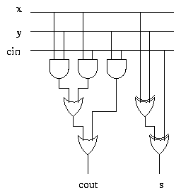
Implementing the Adder
We now know that
and therefore we can easily construct a circuit which implements a
single bit adder.
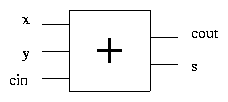
A single bit adder is usually represented as follows.
Multi-Bit Addition
Addition of multi-bit numbers is achieved by chaining single bit
adders together. For example, here is a four bit adder. The inputs are
x and y, expressed in binary as x3x2x1x0 and y3y2y1y0,
and the result is s, expressed in binary as s4s3s2s1s0.
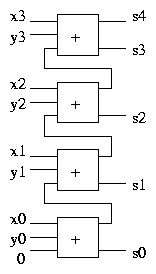
The carry out from each adder is fed into the carry in of the next
adder. The carry in of the adder for the least significant bit is
connected to 0.
Note that if two n bit numbers are added together, the result can
always be expressed in n+1 bits: if x < 2n and y < 2n then
x+y < 2n + 2n = 2(n+1).
Half Adders
In effect we have directly implemented addition of three binary
digits. Let's consider addition of just two digits, which is obviously
more fundamental, even though it does not directly correspond to the
original calculation.
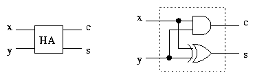
Adding two bits x and y produces a sum s and a carry c:
We can see at once that c = xy and s = x Ċy. Using one
AND gate and one XOR gate we can implement a half adder,
which we represent like this:
As the name suggests, two half adders can be combined to produce a
full adder.
Two Halves Make a Whole
The following circuit uses two half adders to implement a full adder.
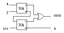
Exercise Use a truth table to check that this circuit is
correct.
This implementation of the adder uses 2 AND gates, 2 XOR gates,
and 1 OR gate. Our original implementation used 3 AND gates, 2
XOR gates, and 2 OR gates. Somehow, splitting the adder into two
half adders has saved an AND gate and an OR gate! This issue is
explored by the following
Exercise
The full adder circuit on Slide 3 calculates
Recall that xcin+ ycin = (x + y)cin. Using this fact, modify the
full adder circuit to remove one of the gates. Redraw the circuit from
Slide 6, replacing each half adder with an AND gate and an XOR
gate. Write down the equations which this circuit is calculating. You
now have two circuits, one of which calculates xy + (x + y)cin and
the other of which calculates xy + (x Ċy)cin. Why are these two
formulae equivalent? Check it with truth tables, and also try to
produce an explanation. The equations calculated by the second circuit
(using the half adders) use 6 logical operations. Why does the circuit
itself only contain 5 gates?
Ripple Carry
The electronic implementations of logic gates do not work
instantaneously - when the inputs change there is a short delay,
perhaps a few nanoseconds, before the outputs change. When a multi-bit
adder is constructed from single-bit adders, the calculation of each
bit of the result involves more delay than the calculation of the
previous bit. This is because the carry bits have to propagate all the
way along the circuit. For this reason, the multi-bit adder we have
presented is known as a ripple carry adder. The longer the
sequence of bits being added, the longer the delay.
The delay caused by the ripple carry design doesn't matter for small
adders, but when adding longer words in a fast microprocessor, it can
become very significant. More complex adder designs exist, which use
various shortcuts to calculate carry bits without the need to
propagate them along the whole word. We won't consider such
lookahead carry designs in this course - wait for next year,
or consult the books.
File translated from
TEX
by
TTH,
version 2.78.
On 27 Jul 2001, 10:19.