CF1 Lecture Notes - Part 2
W P Cockshott
Table
of Contents
2.1 Block Diagram of Typical Computer
2.2 Input/output (I/O) Subsystem
2.3 Memory-mapped I/O Structure
2.5 Typical Structure of Main Memory
3 Programming Model for the 8086
Map of the first megabyte of PC memory
You can obtain help by typing a ?
Tutorial on protected mode addressing
Instruction Repertoire - types of operation
[label] DB initialvalue [,initialvalue]
10 I8086 Assembler Program: Global View
Assembler Directives (aka Pseudo-ops)
Assembly Language Instructions
11 Pseudo-Ops or Assembler Directive Mnemonics
12 Opcode or Instruction Mnemonics
13 Format of Assembly Language Statements
14 INTRODUCTION TO I8086 A.L.P.
Base-indexed with displacement
16 Addressing Modes and Operands
17 Code generation for 8x86 processors
Low Level Program Control Structures
Second practical for Assembler Level
Programming
Appendix a The abstract machine
AppendiX B Predefined PC Hardware and Software
Interrupts
1.1.1
Figures
Figure 1 abstract diagram of
computer
Figure 5 Disk
Surface being written
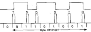
Figure 6 FM
disk encoding used in early floppies
• Figure 7
MFM encoding used in modern floppies
Figure 8
Partitions and partition table
Figure 9
synchronoous serial packet
Figure 10
Asynchronous serial transmission
Figure 11 stack after entry to ISR in 32-bit
mode
Figure 12 stack after entry to ISR in 16-bit
mode
1.1.2
2.1 Block Diagram of Typical Computer
Figure 1 abstract diagram of computer

2.2 Input/output (I/O) Subsystem

Figure 2 i/o subsystem
2.3 Memory-mapped I/O Structure

Figure 3Memory mapped I/O
2.4 Memory Structure
Most, if not all, modern day computers incorporate at least two types of main memory device - Read Only Memory (ROM) and Random Access Memory (RAM).
2.4.1 Read Only Memory (ROM)
This type of memory, as its name suggests, can only be read from. More importantly, the contents of such memory devices are non-volatile which means that their contents are not lost when the power is switched off. This is a necessary requirement to be able to ‘boot’ (start from a power off state) a computer as it must get (at least) its first few instructions from such a device. The (rest of the) operating system is then, typically, loaded from a magnetic media such as tape, floppy disk or hard disk. Some computers keep the whole of their operating system in ROM although this has the disadvantage that it cannot be as easily updated as changing the (contents of) magnetic media.
2.4.2 Random Access Memory (RAM)
more accurately called Read/Write Memory (RWM) - the contents of which can be written as well as read. However, it is, more often than not, volatile in that it loses its contents when power is switched off. Most computers have much more RAM than ROM as most programs, including the operating system, are loaded into this type of memory.
2.5 Typical Structure of Main Memory
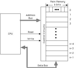
Figure 4Main memory
2.6 Memory Organisations
7......0 15......8 7......0 15......8 7......0
-------- ----------------- -----------------
0 1 | 0 0 | 1
-------- ----------------- -----------------
1 3 | 2 2 | 3
-------- ----------------- -----------------
2 5 | 4 4 | 5
-------- ----------------- -----------------
3 7 T | S 6 6 T | S 7
-------- ----------------- -----------------
4 9 I | R 8 8 I | R 9
-------- ----------------- -----------------
5 11 G | N 10 10 G | N 11
-------- ----------------- -----------------
S 6 | |
-------- ::::::::::::::::: :::::::::::::::::
T 7 65533 | 65532 65532 | 65533
-------- ----------------- -----------------
R 8 65535 | 65534 65534 | 65535
-------- ----------------- -----------------
I 9 (b) (c)
--------
N 10 --------
G 11 -------- 12
--------
::::::::
65534
--------
65535
(a)
a. byte-addressable memory for an 8-bit processor.
b. byte-addressable memory for a 16-bit processor (a so-called “Little Endian” such as the Intel 8086).
c. byte-addressable memory for a 16-bit processor (a “Big Endian” such as the Motorola 68000).
IDE disks
This section gives an overview of how an IDE disk is organised and accessed.
Surfaces
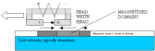
The disk is made up of a number of surfaces
on each of which there is a disk head, set up to read it.
Figure 5 Disk Surface being written
At any one time, information can only be read from one diskhead.
This limitation stems from the means by which heads are positioned on tracks. The tracks are very narrow, and, due to flexing and thermal expansion, servos are required to keep heads above the tracks. Since there is only one disk head actuator, one can not ensure that more than one head at a time is precisely centered on a track.
Figure 6 FM disk encoding used in early floppies
• Figure 7 MFM encoding used in modern floppies
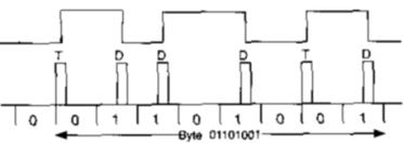
Note that MFM encoding uses fewer timing transitions, thus for a given number of flux domains it can store more bits.
cylinders
The heads all move in synchrony under the influence of a single positioning mechanism. This moves the complete set of heads so that they are all above the same track on the corresponding surfaces. The set of tracks that can be read with the heads in a given position is termed a cylinder
tracks and sectors
start of
track mark
SYNC: 10 byte 00
IAM: 2 byte a1 fc
GAP 1: 11 byte 4e
The tracks are divided into a number of sectors. Each sector contains labels which identify it, along with error correction information. A typical sector contains 512 bytes of useable data.
disk sector
SPD: 7 byte 4e
SYNC: 10 byte 00
IDAM: 2 byte a1 fe
ID: 4 byte cyl head sec flag
ECC: 4 byte ECC value
GAP 2: 5 byte 00
SYNC: 10 byte 00
DAM: 2 byte a1 f8
data: 512 data byte
ECC: 4 byte CRC value
GAP 3: 15 byte 00
End of track mark
GAP 4: about 56 bytes of 00
The IDE cable
IDE disks communicate with the computer using a 40 way cable that is a logical extension of the ISA bus, containing a subset of the bus signals.
Table 1 IDE interface
|
Dir |
IDE signal |
Pin |
Signal meaning |
|
o |
RESET |
1 |
reset drives |
|
b |
GND |
2 |
ground |
|
b |
DD7 |
3 |
data bus bit 7 |
|
b |
DD8 |
4 |
data bus bit 8 |
|
b |
DD6 |
5 |
data bus bit 6 |
|
b |
DD9 |
6 |
data bus bit 9 |
|
b |
DD5 |
7 |
data bus bit 5 |
|
b |
DD10 |
8 |
data bus bit 10 |
|
b |
DD4 |
9 |
data bus bit 4 |
|
b |
DD11 |
10 |
data bus bit 11 |
|
b |
DD3 |
11 |
data bus bit 3 |
|
b |
DD12 |
12 |
data bus bit 12 |
|
b |
DD2 |
13 |
data bus bit 2 |
|
b |
DD13 |
14 |
data bus bit 13 |
|
b |
DD1 |
15 |
data bus bit 1 |
|
b |
DD14 |
16 |
data bus bit 14 |
|
b |
DDO |
17 |
data bus bit 0 |
|
b |
DD15 |
18 |
data bus bit 15 |
|
p |
GND |
19 |
ground |
|
|
|
20 |
pin 20 mark |
|
i |
DMARQ |
21 |
DMA request |
|
p |
GND |
22 |
ground |
|
o |
DIOW |
23 |
write data via I/0 channel |
|
p |
GND |
24 |
ground |
|
o |
DIOR |
25 |
read data via I/0 channel |
|
p |
GND |
26 |
ground |
|
i |
IORDy |
27 |
I/0 access complete (ready) |
|
i |
SPSYNC |
28 |
spindle synchronization |
|
o |
DMACK |
29 |
DMA acknow ledge |
|
p |
GND |
30 |
ground |
|
i |
INTR Q |
31 |
interrupt request |
|
i |
IOCS16 |
32 |
indicates 16 bit transfer |
|
o |
DA1 |
33 |
address bus 1 |
|
i |
PDIAG |
34 |
passed diagnostic from slave |
|
o |
DAO |
35 |
address bus 0 |
|
o |
DA2 |
36 |
address bus 2 |
|
o |
CS1Fx |
37 |
chip select for base addr. 1f0 |
|
o |
CS3Fx |
38 |
chip select for base addr. 3f0 |
|
i |
DASP |
39 |
drive activelslave present |
|
p |
GND |
40 |
ground |
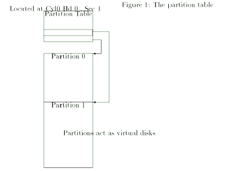
Partitions
Figure 8 Partitions and partition
table
Parallel printer interface
Table 2 Parrallel printer interface
|
25 pin |
36 pin |
Signal |
Description |
|
1 |
1 |
strobe |
low signal level transmits data to printer |
|
2 |
2 |
DO |
data bit 0 |
|
3 |
3 |
Dl |
data bit 1 |
|
4 |
4 |
D2 |
data bit 2 |
|
5 |
5 |
D3 |
data bit 3 |
|
6 |
6 |
D4 |
data bit 4 |
|
7 |
7 |
D5 |
data bit 5 |
|
8 |
8 |
D6 |
data bit 6 |
|
9 |
9 |
D7 |
data bit 7 |
|
10 |
10 |
-ack |
low level indicates that printer received |
|
|
|
|
one character and is able to receive more |
|
11 |
11 |
BSY |
high level of signal indicates |
|
|
|
|
- character received |
|
|
|
|
- printer buffer full |
|
|
|
|
- printer initialization |
|
|
|
|
- printer offline |
|
|
|
|
- printer error |
|
12 |
12 |
PAP |
high level indicates out of paper |
|
13 |
13 |
select |
high level indicates that printer is on-line |
|
14 |
14 |
-LF |
auto line feed; low level indicates that |
|
|
|
|
printer issues line feed automatically |
|
15 |
32 |
-err |
low level indicates |
|
|
|
|
- out of paper |
|
|
|
|
- printer offline |
|
|
|
|
- printer error |
|
16 |
31 |
-init |
low level initializes printer |
|
17 |
36 |
-selectIn |
low level selects printer |
|
18-25 |
19-30,33 |
ground |
ground 0 V |
|
|
16 |
logical ground |
0v |
|
|
17 |
case |
protective ground of case |
|
|
18 |
not used |
+5V |
|
|
34 |
unused |
|
|
|
35 |
unused |
pulled to 5v by 4.7kOhm resistor |
V24 or Rs232 Interface
Serial transmission
Bits sent 1 at a time over a single line. One clock cycle per bit.
Two types of serial transmission, synchronous and asynchronous.
Synchronous
Clock signal sent with the data
Bytes transmitted in a continuous stream
Synchronisation chars sent first
![]() Figure 9 synchronoous serial packet
Figure 9 synchronoous serial packet
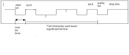
Clock signals generated locally at receiver and transmitter from quartz crystal oscillators.
These clocks are synchronised by a start bit at the beginning of every character.
Figure 10 Asynchronous serial
transmission
Error conditions
Overrun
Overrun error: if data is arriving in the receiver faster than it is read from the receiver buffer register by the CPU, then a later received byte may overwrite the older data not yet read from the buffer. This is called an overrun error.
Parity
Parity error: if none of the above indicated errors has occurred and the byte has been received seemingly in a correct form, a parity error may still be present, that is, the calculated parity doesn’t coincide with the set one.
Parity of a character is computed using the xor of all of its bits.
Parity can be set to be even or odd by manipulating the top bit of the byte. With even parity this is set to ensure that the xor of all 8 bits is 0, with odd parity that the xor of all 8 bits is 1.
Table 3 Examples of parity
|
Char |
Binary 7 bit char |
XOR of char |
8 bits with even parity |
8 bits with odd parity |
|
A |
100 0001 |
0 |
0100 0001 |
1100 0001 |
|
B |
100 0010 |
0 |
0100 0010 |
1100 0010 |
|
C |
100 0011 |
1 |
1100 0011 |
0100 0011 |
|
W |
101 0111 |
1 |
1101 0111 |
0101 0111 |
Physical standard
The standard defines the mechanical, electrical, and logical interface between a data terminal equipment (DTE) and a data carrier equipment (I)CE). The DTE is the computer , the DCE is the modem. The RS-232C standard defines 25 lines between DTE and DCE, and thus a 25-pin plug. Most are reserved for a synchronous data transfer and are not used for on PCs. For Asynchronous transfer only eleven of the RS-232C signals are required. IBM defines a 9-pin connection for its serial interface, where two of the usually present RS232C lines are missing. Table shows the corresponding signals for 25 and 9-pin plugs.
|
25 pin |
9 pin |
Signal |
Direction |
Description |
|
1 |
- |
|
|
protective ground |
|
2 |
3 |
TD |
PC ®MODEM |
transmitted data |
|
3 |
2 |
RD |
MODEM ® PC |
received data |
|
4 |
7 |
RTS |
PC ®MODEM |
request to send |
|
5 |
8 |
CTS |
MODEM ® PC |
clear to send |
|
6 |
6 |
DSR |
MODEM ® PC |
data set ready |
|
7 |
5 |
|
|
signal ground (common) |
|
8 |
1 |
DCD |
MODEM ® PC |
data carrier detect |
|
20 |
4 |
DTR |
PC ®MODEM |
data terminal ready |
|
22 |
9 |
RI |
MODEM ® PC |
ring indicator |
|
|
|
|
|
|
You should understand the following control signals between PC and MODEM
RTS (Request to Send): The PC asks the MODEM if it can send a byte.
CTS (Clear to Send): this signal from the MODEM is a reply to RTS and indicates that the PC can output data.
DCD (Data Carrier Detect): the MODEM activates the DCD signal to show that it has recieved a valid transmission frequency from the remote site - typically the internet ISP.
DSR (Data Set Ready): MODEM tells the PC it is switched on, and has finished any initial exchange of messages with the remote modem.
DTR (Data Terminal Ready): the signal from the PC indicates the PC is switched on and capable of communicating with the modem. If this goes down the modem hangs up the telephone call.
The RI (ring indicator) signal informs the PC that a ring has occurred on the phone line going into the MODEM. If you set up your computer to allow remote logins this is used to alert the computer that an incomming call is occurring.
The major structural components of a CPU are:
· Control Unit: Controls the operation of the CPU
· Arithmetic and Logic Unit: Performs the computer’s data processing functions
· Registers: Provides storage internal to the CPU
· CPU Interconnection: Some means of communication between the CU, ALU, and registers.
The function of the CPU is to:
· Fetch Instructions
· Interpret Instructions
· Fetch data (if required)
· Process data (if required)
· Write data (if required)
Register Organisation
The registers in the CPU serve two functions:
User-Visible Registers: These enable the programmer to minimise external memory references by optimising usage of registers.
Control and Status Registers: These enable the CU to control the operation of the CPU.
User-Visible Registers
These can be categorised as follows:
General Purpose
Data
Address
Condition Codes
In some m/cs General Purpose registers may either be used for Data or Address. In a completely orthogonal IS any GP register can contain the operand(s) for any opcode. Often, however, there are restrictions.
Control and Status Registers
These, in general, are not visible to the user.
Two registers are essential to instruction execution:
Program Counter (PC): Contains the address of an instruction to be fetched.
Instruction Register (IR): Contains the instruction most recently fetched.
All CPU designs include a register often called the Program Status Word (PSW) that contains status information such as condition codes plus other status information.
Pentium
The Pentium is a 32 bit processor. It has 8 x 32 bit general purpose registers organised as follows:
+-----------------+
| eax |
+-----------------+
| ebx |
+-----------------+
| ecx |
+-----------------+
| edx |
+-----------------+
| ebp |
+-----------------+
| ebx |
+-----------------+
| esi |
+-----------------+
| edi |
+-----------------+
16/32 bit use
To retain backward compatibility with the previous 16 bit processors produced by intel , 8086 and 80186, 80286, the intel 32 bit processors (80386, 80486, P5, P6) allow you to use the lower 16 bits of each general purpose register as a 16 bit register. These are then known as the AX as opposed to EAX, BX as opposed to EBX register etc. You can at all times continue to use the processor as a 32 bit machine when writing assembler language by specifying the full register name EAX etc. Since, however, we will be writing DOS programs which, for compatibility have to run on older 16 bit intel processors, we will in the exercises use mainly the lower 16 bits of the registers.
3.1.1 Accumulators
15......87......0
AH
AL
<------AX------>
BH
BL
<------BX------>
CH
CL
<------CX------>
DH
DL
<------DX------>
3.1.2 Index Registers
BP
SP
SI
DI
3.1.3 Segment Registers
CS
SS
DS
ES
3.1.4 Status and Control
IP
D I T S Z A P C Flags
The Data Registers
Four registers, named data registers or general purpose registers (GPR), can be used to hold working variables, constants and counters for use in arithmetic and logical calculations. Although they are 16 bits in size they can be used for operations on 8-bit BYTE or 16-bit WORD data. Thus:
15......87......0
AX
<-byte->
<-----word----->
Data Register
Format
Each
GPR has special attributes:
AX (accumulator). AX is called the accumulator register because it is favoured by the CPU for arithmetic operations. Other operations are also slightly more efficient when performed using AX.
BX (base). In addition to the usual GPR functions, BX has special addressing abilities. It can hold a memory address that points to another variable. Three other registers with this ability are SI, DI, and BP.When using the processor in 32 bit mode, any of the 8 GPRs can be used to hold addresses.
CS (counter). This acts as a counter for repeating or looping instructions. Such instructions automatically repeat and decrement CX and quit when it equals 0.
DX (data). This has a special role in multiply and divide operations. E.g. in multiply it holds the high 16 bits of the product.
The Segment Registers
The CPU contains four segment registers, used as base locations for program instructions, data, and stack. In fact, all references to memory on the PC involve a segment register used as a base location.
CS (code segment). Base location of all executable instructions (code) in a program.
DS (data segment). Default base location for variables.
SS (stack segment). Contains the base location of the stack.
ES (extra segment). An additional base location for memory variables.
The Index Registers
Index registers contain the offsets of variables. The term offset refers to the distance of a variable, label, or instruction from its base segment. Index registers speed up the processing of strings, arrays, and other data structures containing multiple elements.
SI (source index). Takes its name from the string movement instructions in which the source string is pointed to by the SI register. It usually contains an offset value from the DS register, but it can address any variable.
DI (destination index). This acts as the destination for string movement instructions. It usually contains an offset value form the ES register, but it can address any variable.
BP (base pointer). Contains an asumed offset from the SS register as does the stack pointer. BP is often used by a subroutine to locate variables that were passed on the stack by a calling program.
Special Registers
The IP and SP registers are grouped together here, since they do not fit into any of the previous categories.
IP (instruction pointer). IP always contains the offset of the next instruction to be executed. CS and IP combine to form the complete address of the next instruction to be executed.
SP (stack pointer). SP contains the offset, or distance from the beginning of the stack segment to the top of stack. SS and SP combine to form the complete top-of-stack address.
Flags Registers
The Flags register is a special 16-bit register with individual bit positions assigned to show the status of the CPU or the results of arithmetic operations. Each relevant bit position is given a name; other positions are undefined:
Bit position
15 14 13 12 11 10 9 8 7 6 5 4 3 2 1 0
x x x x O D I T S Z x A x P x C
0 = overflow S = sign
D = Direction Z = Zero
I = Interrupt A = Auxiliary Carry
T = Trap P = Parity
x = undefined C = Carry
The primary memory of the I8086 is based on byte storage elements addressed by an address bus. In many ways this memory can be treated as if it were data or address registers - albeit more inefficiently. Although the memory is byte addressable it can also be used to store word data by using two bytes. However, word data must be addressed (accessed) on even byte boundaries. Word values are stored with their LSB first followed by the MSB. Diagrams that show memory contents will show memory organised into 16-bit words each of which is made up of two bytes. Thus:
Memory Address Contents
--------1000 41 01
--------
1002 30 31
--------1004 00 2A
--------1006 2F 2B
--------4.0.1.1.1.1 The above memory contents could be interpreted as:
1) Byte values 41 01 30 31 00
at address 1000 1001 1002 1003 1004
2) Word values 0141 3130 2A00 2B2F
at address 1000 1002 1004 1006
3) Combinations of (1) and (2)4) A series of instructions in machine code.
Memory Map of a PC
------------------------------- ^
00000 Interrupt Vector Table |
------------------------------- |
00400 DOS Data Area |
------------------------------- |
Software BIOS |
DOS Kernel, Device Drivers, etc. 640K
Resident part of COMMAND.COM RAM
------------------------------- |
|
Available RAM for transient |
programs |
|9FFFF Transient part of COMMAND.COM v
-------------------------------A0000 EGA/VGA Graphics Buffer -------------------------------B0000 MDA Text Buffer -------------------------------B8000 CGA/EGA/VGA Text Buffer -------------------------------C0000 Reserved
-------------------------------F0000 ROM BIOS
-------------------------------FFFFF (end of address space)
Map of the first megabyte of PC memory
Map of the first megabyte of PC memory
The I8086 can address 1,048,576 bytes of memory (1MB) using a 20-bit address (00000-FFFFF) in what is termed real address mode. The memory is divided between RAM - starting at location 00000 and extending to BFFFF - and ROM - C0000 to FFFFF.
Under DOS, only the first 640K RAM is available for programs. The remaining address space is used by system hardware such as the video display and hard disk controller or by the ROM BIOS ( a firmware portion of DOS).
Video Display
The video display is memory-mapped. This means that each screen position has its own separate address. When DOS writes a character to the display, it calls a subroutine in the ROM BIOS, which in turn write the character directly to the video memory address.
Video RAM varies between 4KB and 1MB in size. For high-resolution VGA colour displays, the amount of memory used (128KB - 1MB) depends on the number of simultaneous colours supported by the video controller card. The monochrome display uses only 4KB, starting at B0000. All other displays are based at location B8000.
Programs often write characters directly to the video display buffer because the method is so fast.
Read-Only Memory (ROM)
Locations C0000 to FFFFF are
reserved for specialised ROM uses, including the hard disk controller and ROM
BASIC.
The ROM BIOS - at F0000 to FFFFF is
the fundamental building block of the PC’s operating system. It contains system
diagnostic and configuration software, as well as the low-level I/O subroutines
used by DOS.
Purpose of the debugger
examine programs
examine files
low level debugging of programs
patch files
disassemble programs
assemble short code fragments
examine system memory
Invoking the debugger
Typing:C:\WINDOWS>debugProduces the outputaddress 16 bytes of data in hex format ascii data• d3C09:0100 0F 00 B9 8A FF F3 AE 47-61 03 1F 8B C3 48 12 B1 .......Ga....H..3C09:0110 04 8B C6 F7 0A 0A D0 D3-48 DA 2B D0 34 00 F8 3B ........H.+.4..;3C09:0120 00 DB D2 D3 E0 03 F0 8E-DA 8B C7 16 C2 B6 01 16 ................3C09:0130 C0 16 F8 8E C2 AC 8A D0-00 00 4E AD 8B C8 46 8A ..........N...F.3C09:0140 C2 24 FE 3C B0 75 05 AC-F3 AA A0 0A EB 06 3C B2 .$.<.u........
Addresses are made up of two portions ssss:dddd where ssss specifies the segment and dddd the offset within segment. These map to physical addresses using the rule: physical address = 16 * segment + offset hence
3c09:0100 maps to0100
3c0903c190
On the x86 family addresses in segment:offset form have a many to one mapping onto physical addresses. eg:
14c1:0100 = 14c0:0110 = 12b1:22000110
14c0014d10 2200
12b1014d10
Note that the display command starts at address 100 hex by default. The segment address denotes the start of free memory. This will vary with the system configuration.
We can display another area of memory by parameterising the d command:
• d 03C09:0000 CD 20 BC 2F 00 9A EE FE-1D F0 4F 03 6D 36 8A 03 . ./......O.m6..3C09:0010 6D 36 17 03 6D 36 97 07-01 01 01 00 02 FF FF FF m6..m6..........3C09:0020 FF FF FF FF FF FF FF FF-FF FF FF FF 1D 29 E6 FF .............)..3C09:0030 3B 29 14 00 18 00 09 3C-FF FF FF FF 00 00 00 00 ;).....
That still operated on segment 3c09, we can chose another segment thus:
• d 10:200010:0020 97 EA 00 F0 97 EA 00 F0-97 EA 00 F0 B2 0C E3 FE ................0010:0030 97 EA 00 F0 97 EA 00 F0-97 EA 00 F0 97 EA 00 F0 ................0010:0040 97 EA 00 F0 97 EA 00 F0-97 EA 00 F0 97 EA 00 F0 ................0010:0050 97 EA 00 F0 97 EA 00 F0-97 EA 00 F0 97 EA 00 F0 ................0010:0060 97 EA 00 F0 97 EA 00 F0-97 EA 00 F0 97 EA 00 F0 ................0010:0070 05 00 F4 30 97 EA 00 F0-97 EA 00 F0 97 EA 00 F0 ...0............0010:0080 00 00 00 00 00 00 00 00-00 00 00 00 00 00 00 00 ................0010:0090 00 00 00 00 00 00 00 00-00 00 00 00 40 00 E1 30 ............@..0
By default the debugger displays a 128 byte section of memory following the address you supply, you can get it to display more or less by specifying a range. The syntax is
d ssss:bbbb,eeeewheressss Segment numberbbbb begining offseteeee end offset
Example:
• d 10:20,300010:0020 97 EA 00 F0 97 EA 00 F0-97 EA 00 F0 B2 0C E3 FE ................0010:0030 97 .
Examining a File
enter some data into a file using an editor.
C:\TMP>edit tempC:\TMP>debug temp• d3C09:0100 54 68 69 73 20 69 73 20-61 20 74 65 6D 70 6F 72 This is a tempor3C09:0110 61 72 79 20 66 69 6C 65-20 63 61 6C 6C 65 64 20 ary file called3C09:0120 74 65 6D 70 0D 0A 77 69-74 68 20 74 77 6F 20 6C temp..with two l3C09:0130 69 6E 65 73 20 6F 66 20-74 65 78 74 20 69 6E 20 ines of text in3C09:0140 69 74 2E 0D 0A 75 05 AC-F3 AA A0 0A EB 06 3C B2 it...u........
The file is displayed in both hex and ascii. Unprintable characters like carriage return (0D) and linefeed (0A) appear as dots.
Modifying memory
This is done with the E for examine command
• e 1003C09:0100 54.41• e 1003C09:0100 41.41 68.42 69.43 73.44-
characters in italic are typed by the user As you type in numbers followed by a space it shows the previous value in that location. If you follow that with a space you move onto the next location. Modification is terminated by pressing a return character.
Registers
registers can be examined and loaded using the r command.
• r ssSS 3C09 printed by the debugger:100 typed in by user• r axAX 0000:12-
The user provides the register mnemonic and the debugger shows its current contents and allows a new value to be typed in. we can then examine the changes in the whole register set by typing r without a parameter
• rAX=0012 BX=0000 CX=0045 DX=0000 SP=FFEE BP=0000 SI=0000 DI=0000DS=3C09 ES=3C09 SS=0100 CS=3C09 IP=0100 NV UP EI PL NZ NA PO NC3C09:0100 41 INC CX
This shows the registers, the flags and the current instruction about to be executed.
Assembly of program fragments
Let us write our first program in machine code: invoke the debugger with ‘a.com’ as a parameter
windows>debug a.com
Use the assemble command a
• a 1003C09:0100 mov ah,2 dos code for print char3C09:0102 mov dl,42 42 is hex for B3C09:0104 int 21 interrupt 21 is DOS3C09:0106 mov ah,0 dos code for halt3C09:0108 int 213C09:010A-
Now disassemble it to check it.
• u 1003C09:0100 B402 MOV AH,023C09:0102 B242 MOV DL,423C09:0104 CD21 INT 213C09:0106 B400 MOV AH,003C09:0108 CD21 INT 21
Write to file and execute
We write the program to file by giving its base address in the bx register, and its length in the cx register and then executing the w command.
• r bxBX 0000:0• r cxCX 0045:10• wWriting 00010 bytes
Quit the
debugger
• q
Display the
program
C:\TMP>dir *.comVolume in drive C is MS-DOS_6Volume Serial Number is 1F5E-6F6DDirectory of C:\TMPA COM 16 03/10/96 15:52 1 file(s) 16 bytes33,636,352 bytes free
run the
program
C:\TMP>aBC:\TMP>
Tracing
You can execute your program a single instruction at a time with the trace command t.
• t 1 AX=0200 BX=0000 CX=0010 DX=0000 SP=FFFE BP=0000 SI=0000 DI=0000DS=3C56 ES=3C56 SS=3C56 CS=3C56 IP=0102 NV UP EI PL NZ NA PO NC3C56:0102 B242 MOV DL,42• t 1 AX=0200 BX=0000 CX=0010 DX=0042 SP=FFFE BP=0000 SI=0000 DI=0000DS=3C56 ES=3C56 SS=3C56 CS=3C56 IP=0104 NV UP EI PL NZ NA PO NC3C56:0104 CD21 INT 21• t 1 AX=0200 BX=0000 CX=0010 DX=0042 SP=FFF8 BP=0000 SI=0000 DI=0000DS=3C56 ES=3C56 SS=3C56 CS=293B IP=60A0 NV UP DI PL NZ NA PO NC293B:60A0 2E CS:293B:60A1 C6069E6000 MOV BYTE PTR [609E],00 CS:609E=00-
Help
You
can obtain help by typing a ?
-?assemble A [address]compare C range addressdump D [range]enter E address [list]fill F range listgo G [=address] [addresses]hex H value1 value2input I portload L [address] [drive] [firstsector] [number]move M range addressname N [pathname] [arglist]output O port byteproceed P [=address] [number]quit Qregister R [register]search S range listtrace T [=address] [value]unassemble U [range]write W [address] [drive] [firstsector] [number]-
3.2
The assembler
The assembler that we will be
using is called A86. It is invoked from the command line using a single line
command:
c>A86 myfile.asm
This generates a new file
myfile.com, which is binary executable program. The program can be invoked by
typing the name of the program file:
c>Myfile
Use the assembler for all
longer or more complicated programs, the debugger is only suitable for
assembling very short programs.
The lowest 1024 byte of memory (00000 - 003FF) contain the interrupt vector table. These are addresses used by the CPU when processing hardware and software interrupts.
The software BIOS includes routines for managing the keyboard, console, printer, and time-of-day clock. These routines come from a hidden system file on every boot disk called IO.SYS.
The DOS kernel is a collection of DOS services that may be called by application programs and are contained in another hidden file called MSDOS.SYS.
Above this kernel resides both file buffers and installable device drivers (loaded from the CONFIG.SYS file) followed by the resident part of COMMAND.COM - the DOS command processor: It interprets commands typed at the DOS prompt and loads and initiates the execution of programs.
PC Boot-Up
Procedure
When a PC is booted (started), the following happens: THe CPU jumps to an initialisation program in the ROM BIOS. A program called the bootstrap loader loads the boot record from a disk. The boot record contains a program that executes as soon as it is loaded. This program in turn loads IO.SYS and MSDOS.SYS and, finally, COMMAND.COM.
The resident part of COMMAND.COM remains in memory all the time: it
issues error messages, has routines to process Ctrl-Break and critical errors.
The initialisation part reads the AUTOEXEC.BAT file; it is used only while DOS
is being loaded. The transient part is loaded into high RAM and interprets DOS
commands typed at the keyboard. Finally, COMMAND.COM takes over and acts as an
interpreter for user commands.
An address is a number that refers
to an 8-bit memory location. In the I8086 they are expressed in one of two
hexadecimal formats:
A 32-bit segment-offset address. which combines a base location (segment) with an offset to represent an actual location. E.g. 08F1:0100
7.0.1.1.1.1 A 20-bit absolute address, which refers to an exact memory location. E.g. 09010
Using 20 bits, the CPU can address up to 1,048,576 of memory but address registers are only 16 bits wide and can only hold a maximum value of 65,535. To solve this apparent dilemma, the CPU combines the segment and offset values to create an absolute address. As the (16-bit) segment value is always understood to have 4 implied zero bits to the right to pad its length to 20 bits, a segment address of 08F1 really represents an absolute location of 08F10.
0 8 F 1 (0)
0000 1000 1111 0001 0000 <- 4 implied bits
The CPU then adds the offset to the segment, yielding the absolute address:
Segment value -> 0 8 F 1 (0)
Add the offset -> 0 1 0 0
Absolute address -> 0 9 0 1 0
Tutorial on protected mode addressing
When operating under what is called Protected Mode, as used by Windows, OS/2, or Linux, a Pentium processor has a more sophisticated way of using the segment registers to compute an address.
I have said up to now that the segment registers are 16 bits long. In fact they are 96 bits long on a pentium, of which, only the top 16 bits can be accessed by the programmer. The remaining 80 bits are accessible to the Control Unit of the chip and are used by it to calculate actual addressses in a 32 bit linear address space.
7.0.2 Extended segment registers
A more accurate picture is then:
visible| invisible to program
16 | 16 32 32 widths
+----+----+--------+--------+CS| sel|type| base | limit |
+----+----+--------+--------+SS| sel|type| base | limit |
+----+----+--------+--------+DS| sel|type| base | limit |
+----+----+--------+--------+ES| sel|type| base | limit |
+----+----+--------+--------+FS| sel|type| base | limit |
+----+----+--------+--------+GS| sel|type| base | limit |
+---------------------------+
The visible
part is called the selector. When a memory location is accessed the processor
goes through the following steps Assume we have an address of the form
DS:offset
1. The offset is compared to the DS limit.
2. If it is greater than the limit an error occurs, indicating for instance an attempt to access outside the bounds of an array.
3. If it is less than or equal to the limit, the DS base is added to the offset to yield the memory address to be fetched.
In DOS mode the hardware ensures that the limit is always 0000FFFF and that given a selector SSSS the base field of the register will contain 000SSSS0. This achieves the result described earlier. Under Windows, the operating system can set up the base and limit fields to point anywhere within the machine’s 32 bit linear address space.
7.1
Any program written in a HLL must be translated into machine language in order to be executed. Thus the set of m/c instructions must be sufficient to express any of the instructions from a HLL. Thus we can categorise the following types:
Data Processing: Arithmetic & Logic
Data Storage: Memory instructions
Data Movement: I/O instructions
Control: Test & Branch instructions
Instruction Repertoire - types of operation
The number of different opcodes varies widely from machine to machine. A typical categorisation is:
Data Transfer
Arithmetic
Logical
Conversion
I/O
System Control
Transfer of Control
Instruction Encoding
An I8086 instruction contains a specification of the operation to be performed, the data size to be used, and information on where the data is to be found. The assembly language form of the instruction contains a mnemonic for the operation, an operation size (where necessary to clarify an operand’s type), and operands specifying information on the data used by the operation. For example:
<mnemonic>
<size> <operand>,<operand>
If an instruction requires two operands, the first operand is the source and the second is the destination. An operand is specified by an addressing mode that tells the CPU how to locate the register or memory address containing the data needed by the instruction.
Instruction Representation
Each instruction is represented by a sequence of bits, sub-divided into fields corresponding to the constituent parts of the instruction - INSTRUCTION FORMAT. In general, more than one format is used. For example, in the I8086 the generic form of an instruction is:
opcode mod reg r/m
[7 0 7 6 5 4 3 2 1 0]
immed-low immed-high
[7 0 7 0]
disp-low disp-high
[7 0 7 0]
During instruction execution the CPU extracts the data from the various fields to perform the required operation.
The opcode (operation code) field is stored in the lowest byte (at the lowest address). All remaining bytes are optional: the ModR/M field identifies the addressing mode and operands; the immed-low and immed-high specify immediate operands (constants); the disp-low and disp-high fields are for displacements added to base and index registers in the more complex addressing modes. Few instructions will contain all of these fields; on average, most instructions are only 2-3 bytes long.
Opcode. The opcode field identifies the general instruction type (MOV, ADD, SUB, and so on) and contains a general description of the operands.
Many instructions have a second byte - the ModR/M byte - which identifies the type of addressing mode being used. For example, the Intel encoding for a 16-bit MOV from a register to any other operand is:
89 /r
where /r means that a ModR/M byte follows the opcode. The ModR/M byte is made up of three fields:
mod reg r/m
11 011 000 = D8
source dest.
reg or r/m Register reg or r/m Register
000 AX or AL 100 SP or AH
001 CX or CL 101 BP or CH
010 DX or DL 110 SI or DH
011 BX or BL 111 DI or BH
Variables are really just symbolic names for locations in memory where data is stored. In assembly language, variables are identified by labels. A label’s offset is the distance from the start of a segment to the beginning of the variable.
A label does not, however, indicate how many bytes of storage are allocated to a variable - it is, in effect, the address of the first byte of a data structure.
Data definition directives are used to allocate storage based on the following pre-defined types:
Directive Defines Bytes
DB Byte 1
DW Word 2
DD Doubleword 4
DF,DP Far pointer 6
DQ Quadword 8
DT Tenbytes 10
Define Byte
The DB directive allocates storage for one or more 8-bit values. The following syntax diagram shows that label is optional, and only one intialvalue is required. If more are suppied, they must be separated by commas:
[label] DB initialvalue [,initialvalue]
Initialvalue can be one or more 8-bit values, a string constant, a constant expression (evaluated at assembly time), pr a question mark (?). If the value is signed, it has the range -128 to +127; if unsigned, the range is 0 to 255. Here are a few examples:
char db ‘A’ ; ASCII charactermin_s db -128 ; min. signed valuemax_s db +127 ; max. signed valuemin_u db 0 ; min. unsigned valuemax_u db 255 ; max. unsigned value
Each value may also be expressed in a different radix. For example, the following variables all contain exactly the same value. Which radix to use is entirely up to the programmer but is usually chosen to reinforce the context of its use. I.e. if a value is to be treated in a ‘character’ context then the definition reflects that. Thus:
char_version db ‘A’ ; ASCII characterhex_version db 41h ; as hexadecimaldec_version db 65 ; as decimalbin_version db 01000001b ; as binaryoct_version db 101q ; as octal
Note: when a hexadecimal number begins with a letter (A-F), a leading zero is added to prevent the assembler from interpreting it as a label.
[Caveat: DEBUG assumes all values are expressed as hexadecimal and, as it does not allow labels, no leading zero is required.]
A list of values may be grouped under a single label, with the values separated by commas. In the following example, list1 and list2 have the same contents:
list1 db 10, 32, 41h,001000010blist2 db 0Ah,20h,’A’,22h
A variable contents may be left undefined by using the question mark
(?) operator. Or a numeric expression can initialise a variable with a value
that is calculated at assembly time. Examples:
count db ?ages db ?,?,?,?,?scrn_size db 80*24
A string may be assigned to a variable, in which case the variable (label) stands for the address of the first byte.
C_string db “Good morning”,0
pascal_string db 12,”Good morning”
Long strings can be made more readable in an AL source program by continuing them over multiple lines without the necessity of supplying a label for each. The following string is terminated by an end-of-line sequence and a null byte:
a_long_string db “This is a string “ db “that clearly is going to take “ db “several lines to store in an “ db “assembly language program.” db 0Dh,0Ah,0 ; EOL sequence + NULL
The assembler can automatically calculate the length of a string by making use of the $ operator which represents the assembler’s current location counter value. In the following example, a_string_len is initialised to 16:
a_string db “This is a string”
a_string_len db $-a_string
A DEBUG Example. Using DEBUG, we can practice defining bytes and moving them between registers and memory. Remember, however, the restriction that labels cannot be used, so that all references to memory must be a numeric address enclosed in brackets. For example:
Statement Comment
A 150 Assemble data at offset 150
db 10,0 Define 2 data bytes
<ENTER> ends assembly
A 100 Assembly code at offset 100h
mOv ax,0 Clear the AX register
mov ah,[150] Move data to AH
add ah,10 Add 10 to AH
mov [151],ah Store AH in memory
int 20 End program
<ENTER> ends assembly
T Trace each instruction
T T T D 150,151 Dump memory at 150-151
Define Word
The DW directive creates storage for one or more 16-bit words. The syntax is:
[label] DW initialvalue
[,initialvalue]
Initialvalue can be any 16-bit value from 0 to 65,535 (FFFFh) or -32,768 (8000h) to +32,767 (7FFFh) if signed, a constant expression (evaluated at assembly time), or a question mark (?) to leave a variable uninitialised.
Reversed Storage Format. The assembler reverses the byte in a word value when storing them in memory - little-endian format; the lowest byte occurs at the lowest address. When the variable is moved to a 16-bit register, the CPU reverses the bytes.
Pointers.
The offset of a variable or subroutine may be stored in another variable. In
the next example, the assembler sets listPtr to the
offset of list. Then listPtrPtr
contains the address of listPtr. Finally, aProcPtr
contains the offset of a label called clear_screen.
list dw 256,257,258.259
listPtr dw list
listPtrPtr dw listPtr
aProcPtr dw clear_screen
A DEBUG Example. Using DEBUG, we can practice defining words and moving them between registers and memory. For example:
Statement Comment
A 150 Assemble data at offset 150
dw 1234,5678 Define 2 data words
<ENTER> ends assembly
A 100 Assembly code at offset 100h
mov ax,[150] Move 1234 to AX
mov bx,[152] Move 5678 to BX
add ax,2 AX := 1236
mov [154],ax Store 1236 at offset 154
mov [150],bx Store 5678 at offset 150
int 20 End program
<ENTER> ends assembly
T Trace each instruction
T T T T
D 150,155 0150: 78 56 78 56 36 12
Define Doubleword
The DD directive creates storage for one or more 32-bit doublewords. The syntax is:
[label] DD initialvalue
[,initialvalue]
Initialvalue can be any 32-bit value up to FFFFFFFFh, a segment-offset address, a 4-byte encoded real number, or a decimal real number. The bytes are stored in little-endian format, i.e. the value 12345678h would be stored in memory as:
offset: 00 01 02 03
value: 78 56 34 12
You can define either a single doubleword or a list of doublewords. In the example that follows, far_pointer1 is uninitialised and the assembler automatically initialises far_pointer2 to the 32-bit segment-offset address of subroutine1:
signed_val dd -2147483648
far_pointer1 dd ?
far_pointer2 dd subroutine1
DUP Operator
The DUP operator only appears after a storage allocation directive (DB, DW,...). DUP allows for the repetition of one or more values when allocating storage. This is especially useful when allocating space for a table or array. For example:
db 20 dup(0) ; 20 bytes, all zeroed
db 20 dup(?) ; 20 uninitialised bytes
db 4 dup(‘ABC’) ; 12 bytes: ‘ABCABCABCABC’
The DUP operator may also be nested. The first example below creates storage containing (in ASCII) 000XX000XX. The second example creates a 2-dimensional word table of 3 rows by 4 columns:
aTable db 4 dup( 3 dup(‘0’), 2 dup(‘X’) )
anArray dw 3 dup( 4 dup(0) )
Type Checking. When a variable is created using DB, DW, etc., the assembler gives it a default attribute (byte, word, etc.) based on its size. This type is checked on referencing the variable and an error results if the types do not match. So:
count dw 20h
...mov al,count ; error: operand sizes must match
To overcome type checks requires the use of a LABEL directive to create a new name (and associated type) at the same address. Thus:
count_low label byte ; byte attribute
count dw 20h ; word attribute
...mov al,count_low ; retrieve low byte of count
mov cx,count ; retrieve all of count
9.0
9.0.1.1.1.1
Created on 25 Oct
1995
3.2.1.1.1.1.1.1.1 Duncan Smeed <duncan@cs.strath.ac.uk>
3.2.1.1.1.1.1.1.2 Updated 1 Oct by Paul Cockshott wpc@dcs.gla.ac.uk
3.2.1.1.1.1.1.1.3 Updated further by Paul Cockshott Jan 2000
Typically, an Assembly Language Program (ALP) is divided into three sections that specify the main components of a program. In some cases these sections can be inter-mixed to provide for better design and structure.
Assembler Directives (aka Pseudo-ops)
These are instructions supplied by the user to the assembler for defining data and symbols, setting assembler and linking conditions, and specifying output formats, etc. The directives do not produce machine code.
Assembly Language Instructions
These are the actual I8086 instructions.
Data Storage Directives
These allocate data storage locations containing initialized or uninitialized data.
Such mnemonics are not converted into machine code but are directives to the actual assembler. For example:
DOSSEG - Specifies a standard segment order for the code, data and stack segments.
PROC - Identifies the first executable instruction: the program entry point.
END - Program End. This informs the assembler that the program source is finished.
These are converted by the assembler into the equivalent machine code instructions. For example:
MOV - to move data, i.e. memory to register
ADD - to add two data values
AND - to logically AND two data values
In general an AL statement can contain up to four fields. Namely:
[name]
[mnemonic] [operands] [comment]
[Name]
A name identifies a label, variable, symbol or keyword.
Variable and Constants. A name used before a memory allocation directive identifies a location where data are stored in memory. One may also use a name to define a constant, as shown below:
count1 db 50 ; a variable
max_col equ 80 ; a constant
Label If a name appears next to a program instruction, it is called a label. Labels serve as place markers whenever a prgram needs to jump or loop from one location to another.
Keyword A keyword, or reserved word, always has some predefined meaning to the assembler. It may be an instruction or it may be an assembler directive. Examples are MOV, PROC, ADD, AX, and END. Keywords cannot be used out of context or as identifiers. For example, the use of add as a label is illegal:
add: mov ax,10
Rules for Valid Names
These vary from assembler to assembler. Most should accept labels that adhere to the following rules:
The name must start in the first column and be terminated by a :
It may contain six characters, the first of which must be alphabetic and the others alphanumeric*
The name should not be the same as an instruction mnemonic or other reserved words (e.g. ADD, MOV, END, AX)
The name given to the label should be unique within the program.
typical I8086 assemblers for the PC are less restricted than this - e.g. allowing up to 31 character names and including ?_@$. in the set of characters accepted. However, the linker may impose its own restrictions.
[Mnemonic]
This field contains the mnemonic of:
an instruction (e.g. MOV, ADD) or,
a pseudo-op (e.g. PROC, END)
To distinguish labelled statements from unlabelled ones the opcode field of an unlabelled statement must NOT start in the first column.
[Operands]
For those instructions that require operands then this field contains one or more operands separated by commas (e.g. registers or addresses of data to be operated upon by the instruction in the op-code field.
[Comment]
The remainder of the statement is the comment field. Comments in the program are for documentation purposes only and are ignored by the assembler. Some assemblers require this field to start with a special character, such as ‘;’.
Comment-Only Statements
The exception to the format of label, op-code, operand and comment is that if a line starts with a special comment-line character, usually ‘;’, then the whole line is treated as a comment.
Field Separators
In general, the fields are separated by spaces and if the label field is NOT present it must be replaced by at least one space. To improve the appearance of the program it is wise to position the fields at particular column positions (e.g. at tab stops). .For example, contrast the following two programs - one with an untidy layout and the other with a neat layout.
;1) Untidily laid out example program
mov ax,[150] ; Move 1234 to AXmov bx,[152] ;Move 5678 to BXadd ax,2 ;AX := 1236
mov [154],ax ; Store 1236 at offset 154
mov [150], bx ; Store 5678 at offset 150
int 20 ; End program;2) Neatly laid out example programmov ax,[150] ; Move 1234 to AXmov bx,[152] ; Move 5678 to BXadd ax,2 ; AX := 1236mov [154],ax ; Store 1236 at offset 154mov [150],bx ; Store 5678 at offset 150int 20 ; End program
Addressing Modes
As we have seen an instruction consists of
the op-code that tells the process what instruction to perform and,
the operand or address field which tells the processor where to find that data to be operated upon. This address is known as the Effective Address (EA).
To determine the EA, the processor uses one of a number of addressing modes that are defined by the operand field of the instruction. Getting the EA from the addressing mode may be quite simple (e.g. the operand is [the contents of] a data register) or complex (e.g. the operand is in memory, the address of which is contained in an address register).
The I8086 supports a number of addressing modes, shown by the following addressing mode (AM) table. In the table, a displacement is either a number or the offset of a variable. The EA of an operand refers to the offset (distance) of the data from the beginning of a segment. BX and BP are base registers, and SI and DI are index registers. In many instructions the operand can only be specified by certain addressing modes.
Register
AX Effective address (EA) is a register
BL
DI
Immediate
10 EA is that part of the instruction opcode
‘A’ that represents the constant
200h
Direct op1 EA is a displacement
bytelist
[200]
Register Indirect
[bx] EA is the contents of a
[si] base or index register
[di]
Based or Indexed
list[bx] EA is the sum of a base
[si+list] or index register and a displacement
[bp+4]
list[di]
[bp-2]
Base-indexed
[bx+si] EA is the sum of a base register and
[bx][di] an index register
[bp-di]
Base-indexed with displacement
[bx+si+2] EA is the sum of a base register,
list[bx+si] an index register, and a displacement
list[bx][si]
Why are there so many(!) AM? Mainly because they make programming more convenient, especially when manipulating data structures such as arrays. For example, the Base-indexed AM lets you set BX and SI to the row and column offsets, respectively, of any element in the table.
Invariably, when referring to an AM, we also refer to the type of operand used. The use of a register operand, for example, implies the register AM.
Register Operand
A register operand may be any 8-bit or 16-bit register. In general, this AM is the most efficient because registers are part of the CPU and no memory access is required. Some examples using the MOV instruction are:
mov ax,bxmov cl,almov si,ax
Immediate Operand
An immediate operand is a constant expression, such as a number, a character, or an arithmetic expression. The assembler must be able to determine the value of an immediate operand at assembly time. Its value is inserted directly into the machine instruction.
Direct Operand
A direct operand refers to the contents of memory at the offset of a variable. The assembler keeps track of every label, making it possible to calculate the effective address of any direct operand. In the following example, the contents of memory location count are moved into AL:
count db 20
.
.
mov al,count
OFFSET Operator.
When it is necessary to move the offset of a label into a register or variable, the OFFSET operator does the trick. Since the assembler knows the offset of every label as the program is being assembled, it simply substitutes the offset value into the instruction. Assuming that the offset of the variable aWord in the following example is 0200h; the MOV instruction would move 200h directly into BX:
aWord dw 1234
.
.
mov bx,offset aWord; the above assembles as: mov BX,0200
Indirect Operand
When the offset of a variable is placed in a base or index register, the register becomes a pointer to the label. For variable containing a single element this is of little benefit but for a list of elements a pointer may be incremented - within a loop, say - to point to each element.
Example. If we create a string in memory at location 0200h and set BX to the base offset of the string, we can access any element in the string by adding its index to BX. The letter ‘F’ is at index 5 in the following example:
;indices are: 0123456aString db “ABCDEFG”
.
.
mov bx,offset aString ; BX = 200
add bx,5 ; BX = 205
mov dl,[bx] ; DL = ‘F’
Segment Defaults.
If BX, SI, or DI is used, the EA is by default an offset from the DS (data segment) register. BP, on the other hand, is an offset for the SS (stack segment) register. Assuming that the stack segment and data segment are at different locations, the following two statements would have different effects even if the SI and BP registers contained the same values:
mov dl,[si] ; look in the data segmentmov dl,[bp] ; look in the stack segment
If one really must use BP in the data segment, a segment override operator forces the issue:
mov dl,[si] ; look in the data segment
mov dl,ds:[bp] ; ditto
Based and Indexed Operands
Based and indexed operands are basically the same: A register is added to a displacement to generate an EA. The register must be SI, DI, BX or BP. A displacement is either a number or a label whose offset is known at assembly time. The notation may take several equivalent forms:
Register Added to an Offset
mov dx,array[bx]
mov dx,[bx+array]
mov dx,[array+bx]
Register Added to a Constant
mov ax,2[si]
mov ax,[si+2]
mov dx,-2[bp]
mov dx,[bp-2]
Example. If we create an array of bytes in memory at location 0200h and set BX to 5, BX can then be used to access the 6th element of the array (note: array indices start at 0).
;indices: 0 1 2 3 4 5 6 7 8
array db 00,02,04,08,16,32,64,128,256.
.
mov bx,5mov al,array[bx] ; AL = 32
Based-Indexed Operand
An operand’s EA is formed by combining a base register with an index register. Suppose BX = 202h and SI =6; then the following instuction would calculate an EA of 208h:
mov al,[bx+si]
This technique is often useful for two-dimensional arrays, where BX can address the row and SO the column:
array db 10h,20h,30h,40h,50hdb 60h,70h,80h,90h,A0h
db B0h,C0h,D0h,E0h,F0h
.
.
mov bx,offset array ; point to array
add bx,5 ; select 2nd row
mov si,2 ; select 3rd col
mov al,[bx+si] ; get element
Two base registers or two index registers cannot be combined, so the following would be incorrect:
mov al,[bx+bp] ; error: 2 base regs
mov dx,[si+di] ; error: 2 index regs
Base-Indexed with Displacement
An operands effective address is formed by combining a base register, an index register, and a displacement.
Using the previous two-dimensional array example, we no longer have to set BX to the beginning of the array - we just set BX to the address of the second row relative to the beginning of the table. This makes the code simpler:
array db 10h,20h,30h,40h,50hdb 60h,70h,80h,90h,A0h
db B0h,C0h,D0h,E0h,F0h
.
.
mov bx,5 ; select 2nd row
mov si,2 ; select 3rd col
mov al,array[bx+si] ; get element
A DEBUG Example. The following example program shows how a variety of addressing modes may be used when accessing elements of an array. The array is located at offset 150, and the sum will be stored at offset 153:
Statement Comment
A 150 Assemble data at offset 150
db 10,20,30,0 1st 3 bytes are array, last is sum
<ENTER> ends assembly A 100 Assembly code at offset 100h
mov bx,150 BX points to the array
mov si,2 SI will be an index
mov al,[bx] Indirect operand
add al,[bx+1] Base-offset operand
add al,[bx+si] Base-indexed operand
mov [153],al Direct operand
int 20 End program
<ENTER> ends assembly T Trace each instruction
. .
. D 150,153 Dump array and sum
Created on 25 Oct 1995
Duncan Smeed <duncan@cs.strath.ac.uk>
http://www.cs.strath.ac.uk/CS/Courses/223/OHP28-2E.html
<!DOCTYPE HTML PUBLIC “-//W3C//DTD HTML 3.2//EN”>
Paul Cockshott
Low Level Program Control Structures
Most computer algorithms contain decision points where code is conditionally executed depending on the status of program variables. Conditional execution and loop constructs are available in high-level languages. The equivalent constructs in assembly language use branch instructions. This section introduces the various forms of I8086 branch instructions and discusses the low level language implementation of high-level language control constructs.
There are two general categories of low level branch:
Unconditional Transfer. The program branches to a new location in all cases; a new value is loaded into the IP, causing execution to continue a the new address.
Conditional Transfer. The program branches if a certain condition is true. The I8086 provides a wide range of conditional transfer instructions that may be combined to make up conditional logic structures. The CPU interprets true/false conditions based on the contents of the CX and Flags registers.
1.1 JMP Instruction
Syntax: JMP SHORT,NEAR PTR,FAR PTR <label>
Action: Program control passes directly to the instruction located at the address <label>.
Notes 1. The SHORT form jumps to label in the range -128 to +127 bytes from the current location (in the same code segment). I.e. an 8-bit signed value is added to the IP. This is especially useful when coding forward jumps since the assembler does not know the destination address until it assembles that part of the program. For example:
label1: jmp short label2
<up to a few dozen insts here...>
...
label2: jmp label1 ; short used
2. The NEAR PTR form tells the assembler that the destination label is in the same code segment; usually this is assumed.
3. The FAR PTR form is required if the jump is to a label outside the current segment.
1.2 LOOP Instruction
The LOOP instruction is the easiest way to repeat a block of statements a specific number of times. CX is automatically used as a counter and is decremented each time the loop repeats.
Syntax: LOOP <label>
Action: 1 is subtracted from the CX. If CX is greater than zero control transfers to <label> which must be -128 to +127 bytes from the current location. If CX = 0 after having been decremented, no jump takes place and control passes to the instruction following the loop.
1.3 Conditional Processing
The Flags (or Condition Code) Register (CCR)
We have seen that JMP is unconditional in that control is always transferred. Conditional transfers of control are a common requirement, typically of the form (in C):
IF (X == 0) Y = 20 ELSE Y = 30;
To support this the iAPX86 has a word sized register called the FLAGS REGISTER with individual bit positions assigned to control the CPU or show the results of arithmetic operations. For conditional processing we are concerned with the way the Zero, Carry and Sign flags show the results of boolean and comparison instructions:
The Zero bit (flag) is set to 1 if the previous instruction gave a zero result, otherwise its 0
The Sign bit takes on the value of the MSBit of the result (given twos complement). If it is 1 then this indicates a negative result.
The Carry bit is set when the result of an unsigned addition is too large for the destination operand or when a subtraction requires a borrow.
The Overflow bit is set when a signed arithmetic operation generates a result that is out of range.
1.4 Boolean Instructions
Boolean instructions are based on boolean algebra operations. These operations allow modification of individual bits in binary numbers, as summarised in the following table:
|
Operation |
Comment |
|
AND |
Result is 1 only when both input bits are 1 |
|
OR |
Result is 1 when either input is 1 |
|
XOR |
Result is 1 only when the input bits differ |
|
NOT |
Result is the reverse of the input (1 <-> 0) |
The first three instructions perform their operations on two 8-bit or 16-bit operands and place their result in the destination operand.
Syntax AND,OR,XOR destination,source
Their operands must be the same size, and only one of them may be a memory operand.
Examples: Assuming that AL contains 10101010b before executing each of the following instructions, the result that would occur after execution is shown as a comment:
AND AL,00001111b ;AL = 00001010b
OR AL,01010101b ;AL = 11111111b
XOR AL,00001111b ;AL = 10100101b
NOT AL ;AL = 01010101b
1.5 Conditional Jumps
These instructions jump (transfer control to a destination address) according to values in the flags register. Their general syntax is:
Jcond <shortlabel>
If the condition cond is TRUE then control is transferred to the address <shortlabel>, otherwise execution continues to the next instruction in sequence.
Table 1: Jumps Based on Unsigned Comparisons
|
Jcond |
Description |
Flag Condition(s) |
|
JZ |
Jump if Zero |
ZF =1 |
|
JE |
Jump if Equal |
|
|
|
(if op1 == op2) |
|
|
JNZ |
Jump if Not Zero |
ZF = 0 |
|
JNE |
Jump if Not Equal |
|
|
|
(if op1 != op2) |
|
|
JA |
Jump if Above |
CF = 0 and ZF = 0 |
|
JNBE |
Jump if Not Below or Equal |
|
|
|
(if op1 > op2) |
|
|
JAE |
Jump if Above or Equal |
CF = 0 |
|
JNB |
Jump if Not Below |
|
|
|
if (op1 >= op2) |
|
|
JB |
Jump if Below |
CF = 1 |
|
JNAE |
Jump if Not Above or Equal |
|
|
JC |
Jump if Carry |
|
|
|
if (op1 < op2) |
|
|
JBE |
Jump if Below or Equal |
CF = 1 or ZF = 1 |
|
JNA |
Jump if Not Above |
|
|
|
(if op1 <= op2) |
|
|
JCXZ |
Jump if CX = 0 |
CX = 0 |
|
JP |
Jump if Parity even |
PF = 1 |
|
JNP |
Jump if No Parity |
PF = 0 |
Table 2: Jumps Based on Signed Comparisons
|
|
|
|
|
Jcond |
Description |
Flag Condition(s) |
|
JG |
Jump if Greater |
ZF = 0 and SF = OF |
|
JNLE |
Jump if Not Less or Equal |
|
|
|
(if op1 > op2) |
|
|
JGE |
Jump if Greater than or Equal |
SF = OF |
|
JNL |
Jump if Not Less |
|
|
|
(if op1 >= op2) |
|
|
JL |
Jump if Less |
SF != OF |
|
JNGE |
Jump if Not Greater or Equal |
|
|
|
(if op1 < op2) |
|
|
JLE |
Jump if Less or Equal |
ZF = 1 or SF != OF |
|
JNG |
Jump if Not Greater |
|
|
|
if (op1 <= op2) |
|
|
JS |
Jump if Signed |
SF = 1 |
|
JNS |
Jump if Not Signed |
SF = 0 |
|
JO |
Jump if Overflow |
OF = 1 |
|
JNO |
Jump if Not Overflow |
OF = 0 |
Comparison Instructions:TEST and CMP
Before executing a conditional jump instruction, the flag bits must be set by executing a previous instruction in the logic of the program. Often the instruction will be an arithmetic operation that produces some result. Other instructions, such as TEST, permit an explicit test of a register or a memory location.
TEST Instruction
The TEST instruction performs an implied (temporary) AND on the destination operand, using the source operand. The flags are affected but neither operand is changed.
Syntax: TEST destination,source
Action: If any matching bit positions are set in both operands, the Zero flag is cleared. It is particularly valuable when you want to know if individual bits in an operand are set.
CMP Instruction
The CMP instruction performs an implied subtraction of the source operand from the destination operand, but neither operand is actually changed.
Syntax: CMP destination,source
Flag Conditions. Generally only three flags are important outcomes from the instruction:
|
After CMP |
Flag Results |
|
Destination < source |
CF = 1 |
|
Destination = source |
ZF = 1 |
|
Destination > source |
CF = 0, ZF = 0 |
The sense of the comparison and resultant branch is <source> cond <destination>, as in:
CMP AL,’9’ compare AL with ‘9’
JLE LABEL jump to LABEL if
AL LE ‘9’,i.e. AL <= ‘9’
Example of compiling while statements
High-level languages provide constructs for conditional code execution and loops. These constructs translate into comparison and jump instructions in assembly language.
Code generated for WHILE
Suppose that we have the while statement:
while ( C1 ) C2
with the Ci standing for expressions.
The effect of the compiler parsing such a statement is to generate abstract machine code that looks like listing 1.
Listing
1
l1:C1
code
condify
code
jumpt
l3
jump l2
l3:C2
code
jump
l1
l2:
Abstract machine
The code shown in listing 1 is not for any one particular type of CPU. It is an abstract machine code. It abstracts from the details of particular machines. The syntax analyser assumes it is producing instructions for this abstract machine. The abstract machine is a general-purpose computer whose instruction set includes all of the operations necessary to implement the semantics of the language that is being translated. On some computers the operations of the abstract machine can be implemented with single instructions. In others, several real machine instructions may be needed to achieve the same effect as the abstract machine instructions.
What is shown in listing 1 is a fairly simple set of abstract machine instructions that are likely to be available to most machines. A full listing of the instructions executed by the abstract machine is given in 10, but we will give a brief outline of the machine here.
The machine is assumed to have four registers:
PC |
Program Counter points at current instruction. |
GP |
Globals Pointer, points at the start of the global variables |
FP |
Frame Pointer, points at the local variables of a procedure |
SP |
Stack Pointer points at the top of the stack. |
On an 8x86 processor these would be mapped to
PC - IP
SP - SP
FP - BP
GP - DS
There are three areas of store:
CS |
The Code Store holds instructions |
STACK |
This holds variables and temporary results |
HEAP |
This holds objects like arrays, strings or structures. |
All instructions are defined in terms of the effect that they produce on the registers and the stores.
Reverse Polish notation
The abstract machine is a stack machine. That is to say arithmetic instructions operate on the top two words on stack. Consider the following expression:
2+4
This works by placing two words on the stack and then adding them as shown in Figure 1.
Step i ii iii
2 4 6 <- top of stack
2
Figure 1: Adding 2 to 4 on the stack
The abstract machine instructions that do this would be:
llint(2)
llint(4)
add
This form of arithmetic in which the operator comes after its operands is termed reverse Polish notation. It is a particularly easy notation to compile into. The general rule for generating code for any binary expression
|
e1 op e2 |
becomes :
generate code for e1
generate code for e2
generate code for op
Reverse Polish notation combined with a recursive descent compiler will automatically generate the right code for expressions with operators of mixed priorities. The expression:
4+2*3
should yield 10. Given the syntax:
<exp3>::=<exp4>[<addop><exp4>]*
<exp4>::=<exp5>[<multop><exp5>]*
<exp5>::=<int-literal>
we obain the parse shown in table 3.
Table 3: Parse and code generation for 4+2 * 3
Parse |
Code produced |
Stack |
exp3 |
|
... |
exp4 addop exp4 |
|
... |
exp5 addop exp4 |
|
... |
4 addop exp4 |
llint(4) |
... 4 |
4 addop exp5 multop exp5 |
|
... 4 |
4 addop 2 multop exp5 |
llint(2) |
... 4 2 |
4 addop 2 multop 3 |
llint(3) |
... 4 2 3 |
4 addop 2 * 3 |
mult |
... 4 6 |
4 + 2 * 3 |
add |
... 10 |
It is easy to translate these abstract instructions into concrete 8x86 instructions since the 80x86 supports a hardware stack. The previous sequence of instructions would generate:
Listing
2
push
4
push
2
push
3
pop
cx
pop
ax
imul
cx
push
ax ;
x
pop
cx
pop
ax ;
y
add
ax,cx
push
ax
The instructions x and y in the above sequence are strictly speaking redundant, and if the compiler has an optimising phase they should be deleted.
Conditionals
The generation of arithmetic instructions is fairly straightforward since computers always have a set of arithmetic machine codes. Handling boolean operations is more problematic.
Consider the operation < which takes two numbers and returns a truth value. In a high level language like S-algol or Pascal truth values have the type boolean, and are represented in memory by a word which contains some non zero value for true and zero for false. Some modern CPUs like the AMD 29000 have opcodes that directly compute this operation, but older ones like the 80x86 series do not. Instead they have comparison instructions which compare two values and set some CPU flags on the basis of the result. In particular the sign and carry flags are set according to the result of comparison. The 80x86 series then provide jump instructions that will conditionally jump on the flags : JL for Jump Less than, JG for Jump Greater than etc.
Suppose we have the source code
if (a<b) X
we want to generate code something like
Listing
3
push
a
push
b
pop
cx
pop
ax
cmp
ax,cx
jl
label1
jump
label2
label1: ...
code for X
label2:
For this sort of construct the setting of CPU flags is quite efficient as a control mechanism. For boolean assignment this is not so suitable. For the statement
p=
a<b
we
need something like
Listing
4
push
a
push
b
pop
cx
pop
ax
cmp
ax,cx
; code to generate a boolean on the stack
jl
label1
push
0 ;*
jump
label2
label1:
push 1 ;*
;
code to perform the assignment
label2: pop
p
The instructions marked with * have to be inserted to convert the values in the flags into a booleanindexflags!conversion to booleans value on the stack.
With a recursive descent compiler 1 the syntax analyser procedure that looks for comparison operations does not know if this comparison is to be called in an if statement or in a boolean assignment or any one of a number of other contexts. What the procedure that analyses comparison expressions does is plant code for a compare instruction and return ‘conditional’ rather than ‘boolean’ as the type produced by the expression. When the code generator is asked to perform a conditional operation it remembers what comparison it was: less than, greater than etc. If at a later stage the syntax analyser discovers that it has a conditional and needs a boolean it calls the code generator to convert the conditional into a boolean by planting code that will plant the appropriate truth value on the stack.
If clauses
If clauses provide an illustration of how conditionals are handled. The syntax analysis procedure for an if clause is given in listing 5. Note how the procedure condify is called to ensure that the condition codes have been set. This is necessary to deal with examples like:
a=
z>y;
if(
a ) COUT << “z > y”;
The if clause tests the boolean variable a. After the compiler has matched the if, it calls the procedure clause to parse the condition. This returns to indicate that the result on the stack is a boolean. The condify procedure finds that the top of the stack is a boolean so it plants code to compare the top of stack with zero. This sets the condition codes and allows the jump to be made. If on the other hand the source had been:
if
(x<y ) COUT << “x < y “
then the call on clause would have set the variable t to condition. Finding that the condition codes were already set, the condify procedure would do nothing. Consider the following pseudo code algorithm
Listing 5
/ ----------------- }
* IF _CLAUSE
this
parses the rule
<ifclause>
::=
if
( <clause> ) <clause> else
<clause>
----------------- \*/i
void if_clause()
{
typerec t1 ; labl l, l1, l3 ;
l1 ¬ newlab ; l ¬ newlab ; l3 ¬ newlab ;
next_symbol ;
clause(t) ; condify(t) ;
jumpt(l) ; jumpop(l3) ; plant(l) ;
{
clause(t1) ; jumpop(l1) ; decsp(t1) ;
mustbe(else_sy) ;
plant(l3) ;
clause(t) ; balance(t, t1) ;
plant(l1) ; release_label(l1) ;
} ;
release_label(l3) ;
} ;
A condition is given in the form of a Boolean expression. If it evaluates TRUE, the code block [denoted Code(T)] is executed. Otherwise, program control passes to the first statement following the code block.
High-Level
Language Construct
IF
<Boolean expression> THEN
code(T)
<rest
of code>
As we have seen instructions such as TEST, CMP, or arithmetic operations set the CCR bits. If the result is FALSE, a branch to a label located at the <rest of code> is executed. In other words, the branch tests the condition under which the code(T) block should not be executed. Therefore, the following type of code sequence would be used:
Low-Level Language Construct
<set CCR bit(s)>
J!cond <endif>
code(T)
<endif> <rest of code>
Note The notation !cond means jump on NOT condition cond. For instance, if cond = GE then use the jump JL.
...An IF (...) example in the style of C:
if (AL == ‘-‘)
DI = DI + 1;
<rest of code>
Low-Level Language Equivalent
CMP AL,25
JNE ENDIF
INC DI
ENDIF <rest of code>
The IF...THEN...ELSE....Construct
Frequently program logic requires an either-or choice. If the condition is TRUE, take one line of action [code(T)]. Otherwise select an alternative action [code(F)].
IF <Boolean expression> THEN
code(T)
ELSE
code(F)
<rest of code>
Low-Level Language Construct
<set CCR bit(s)>
J!cond <else>
code(T)
JMP <endif>
<else> code(F)
<endif> <rest of code>
...An IF (...)...ELSE example in the style of C:
if (AL < 10) AL = AL + ‘0’;
else AL = AL + ‘A’-10;
<rest of code>
Low-Level Language Equivalent
CMP AL,10
JGE ELSE
ADD AL,’0’
JMP ENDIF
ELSE ADD AL,’A’-10
ENDIF <rest of code>
Note Labels as above can
be used to show the parts of the structure and the end of the IF. It is good
programming practice, however, to use labels relevant to the meaning of the
application program.
For loops
For loops in programming languages come in two main
forms. The simplest is the Pascal variant where you write something like
for i:=x to y do ... .
Within the body of the loop, i will take on all the values in the range x to y in turn. Other languages, including C allow a more general variant of the for loop :
for (i=x; i<= y; i+= z ) ... .
In this case z provides the step by which i is to be incremented.
The semantics of the generalised for loop with a variable step size are more complex.
Listing
6
for (i=x; x<=y; i+=
z){
COUT << i;
m= m+i;
}
COUT << m
This is equivalent to the following while loop:
Listing 7
i=x;
while (x <= y)
{
COUT
<< i;
m
=m+i;
i
+= z;
}
COUT << m
What the compiler actually does is similar to translating the for loop into a while loop and then compiling this into machine code. What is done is shown in listing 7.
For loop code
We can see the code generated for the simple loop:
for (i=1;i<= 10 ; i++) ...
in listing 8.
Listing
8
push 1; this location on the
stack
;
will be the variable i
push 10
; forprep sequence
pop cx
pop ax
push ax
sub cx,ax
add cx,2; precompute the
number of times round loop
;minfortest
sequence
l1 loop m1 ;
this is a machine code instruction which
;
tests the CX register
;
if non zero it goes to m1 and decrements CX
pop ax
jmp l2
m1 push cx ;
CX held induction variable
;--------------------- Main
body of loop goes here
; minforstep sequence
pop
cx ; induction variable back in CX register
pop
ax ; increment i
inc
ax
push
ax
jmp
l1 ; go back to the top of the loop
l2:
Note that this takes advantage of special instructions included in the 80286 instruction set to handle simple loops. The loop instruction expects the counter register CX to hold the number of times it is to go round a loop.
We precompute this and load it into CX before the loop starts. During the body of the loop, CX is pushed onto the stack to prevent it being corrupted by a nested loop.
The CASE Structure
This allows a multiway branch by comparing a single value to a list of values. Similar in concept to nested if..then..else constructs.
Listing
9 Low-Level Language Construct
<case> <set CCR bit(s)>
J!cond <case02>
<first case statement>
JMP <endcase>
<case02> <set CCR bit(s)>
J!cond <case03>
<second case statement>
JMP <endcase>
<case03> <set CCR bit(s)>
J!cond <case...>
<third case statement>
JMP <endcase>
<case...> <repeats as above>
...
<endcase> <rest of code>
A CASE construct in the style of C:
Listing
10
switch (argc)
{
case 1: /* No arguments
so...*/
<prompt statements>;
break;
case 3: /* Arguments given
so...*/
<assign statements>;
break;
default: /* Incorrect
arguments */
<default statements>;
break;
}
Listing 11 Low-Level Language
Equivalent
<case> MOV
AL,argc
CMP AL,1
JNE <case02>
<prompt statement>
JMP <endcase>
<case02> CMP
AL,3
JNE <default>
<assign statement>
JMP <endcase>
<default> <default statement>
<endcase> <rest of code>
The CASE Structure: a look-up table implementation
In some circumstances, mainly when a large number of comparisons have to be made, a look-up table (aka an offset table) is created. The assembler can calculate a label’s offset and place it in a variable. The following iAPX86 statements define a table containing the look-up values and addresses of procedures (functions) we want to call:
Listing
12
casetable db
1 ; look-up value
assign ; address of function
db 3
prompt
The following assembler code will attempt to match the case condition with each entry and when found causes a call to the function offset stored immediately after the look-up value:
Listing
13
mov al,argc
mov bx,offset casetable
mov cx,2 ;no. of entries
L1: cmp al,[bx] ; match
found?
jne L2 ; no:
continue
call word ptr [bx+1]; yes: call
jmp L3 ; exit the
search
L2: add bx,3 ; point to next entry
loop L1
; repeat until CX=0
<default statement> ;
default:
L3: <rest of code>
This method involves some overhead (and probably wouldn’t be used for only two case statements as above), but it helps to make the compiled program more efficient.
Variable access
An abstract machine specifies a set of stores and a set of operations on these stores. These stores can have a number of possible types. One class of store is a set of predesignated variables capable of holding an individual word of data. We generally call these registers. In an actual hardware machine the registers will often be implemented by using particularly fast memory chips, or in a microprocessor, by using on-chip memory cells. From the standpoint of abstract machine design this is not important, since an abstract machine is concerned only with the functional specification of a computer. The speed of access to different parts of the store is an implementation optimisation.
The areas of memory defined by the abstract machine are the registers, the code store, the stack, and the heap.
C++, like all C is a recursive language. It is recursive in two senses. It is defined by a recursive grammar and it allows the recursive calling of procedures. This imposes special constraints on the store of the language that are best satisfied by a stack structured memory. Consider the fragment of code shown in listing 14.
Listing 14
{
int
x=3;
int
y=x*getch();
//
position 1
{
int
a = x;
x=y;
y=a;
//
position 2
}
{
int
i:=9+x
if(
i>y ) y=x;
//
position 3
}
}
In this example four variables are defined a,i,x,y, but at no point are more than three of the variables in scope at once. At position 2 the variables x, y,a are in scope and at position 3 the variables x,y,i are in scope. In other words, different variables persist for different periods of time. Variables are only in scope between the point at which they are declared and the end of the block. Because the grammar of C allows blocks to be nested it generates a Last In First Out discipline on the scope rules. The variables in the outermost block remain in scope for the entire program whereas the variables in innermost blocks are discarded first. This lends itself naturally to a stack implementation.
Table 4: Abstract machine code for source in listing 9.14
Address |
S machine code |
Source/Comment |
1 |
ll.int(3) |
int x=3; |
2 |
global(0) |
x ® top of stack |
3 |
getch() |
getch() rightarrow top of stack |
4 |
times |
int y= x*getch() |
|
|
|
! position 1 |
5 |
global(0) |
int a=x |
6 |
global(1) |
y ® top of stack |
7 |
globalassign(0) |
x=y |
9 |
global(2) |
a ® top of stack |
10 |
gloabalassign(1) |
y=a |
|
|
|
! position 2 |
11 |
retract(1) |
! get rid of a |
12 |
ll.int(9) |
9 ® top of stack |
13 |
global(0) |
x ® top of stack |
14 |
plus |
int i=9+x |
15 |
global(2) |
i ® top of stack |
16 |
global(1) |
y ® top of stack |
17 |
le.i |
i<y ® top of stack |
18 |
jumpf(23) |
! if top of stack |
|
|
|
! false goto 23 |
19 |
global(1) |
y ® top of stack |
20 |
globalassign(0) |
x=y |
|
|
|
! position 3 |
21 |
retract(1) |
! get rid of i |
22 |
retract(2) |
! get rid of x and y |
The C code in listing 14 would be equivalent to the abstract-code in table 4.
The evolution of the stack during this process is shown in figure . Variables are accessed by specifying their address relative to the current base of the stack. The variable x is accessed using the operator global(0) since it is at the base of the stack, y is addressed as global(1) as it is at position 1 on the stack etc. It is worth noting that the combination of the C initialising assignment statement
int <variable>= <expression>
with the stack allocation discipline means that many of the store instructions that would be required in a conventional machine architecture are dispensed with. The initial value is simply calculated and then left on the stack. The compiler then just remembers where on the stack it was left.
If the variable was declared at the outer most level the address associated with the variable is given relative to the GP or global pointer register. If a variable is declared in a procedure, then its address is specified relative to the FP or frame pointer register. When generating code, variables are consistently dealt with in terms of their addresses relative to some base register.
Procedures
The most complicated use of the stack in an C-based language is the way in which it is used to implement procedure calls.
8.1 Simple procedures
Global variables are
accessed by offset from some global base register. Local variables are accessed
by an offset from the frame pointer. Suppose we have the following C procedure:
Listing 15
swap(a,b)int
*a,*b;
{
int temp;
temp= *a; *a= *b; *b
= temp;
}
This might generate the following abstract machine code:
|
Address |
S machine code |
Comment |
|
49 |
push(fp) |
! tos ¬ fp |
|
49 |
copy(fp,sp) |
! fp ¬ sp |
|
50 |
retract(-1) |
! reserve space for temp |
|
51 |
local.i(-3) |
! push a, tos ¬ [FP-3] |
|
52 |
deref |
! change to *a tos ¬ [tos] |
|
53 |
localass(1) |
! store in temp |
|
|
|
! [FP+1] ¬ tos |
|
54 |
local.i(-3) |
! a to top of stack |
|
55 |
local.i(-2) |
! b to top of stack |
|
56 |
deref |
! change to *b |
|
57 |
store |
! store in *a [tos] ¬ tos |
|
58 |
locali(-2) |
! push b |
|
59 |
local(1) |
! push temp |
|
60 |
store |
! *b ¬ temp |
|
61 |
retract(1) |
! get rid of temp |
|
62 |
pop(fp) |
|
|
63 |
return |
|
The important thing to note about this is the procedure entry and exit code. When the procedure is entered the FP is saved on the stack and reset to point at the current top of stack. The stack pointer is then advanced to create sufficient space for the local variables (only one in this case). On exit from the procedure the space is released and the FP restored to its previous value before returning. The stored copy of FP on the stack is termed the dynamic link. It links a procedure to the environment in which it was called.
The meaning of the code is made clearer by figure 2. The local variables are accessed by a positive offset from the FP and the parameters by a negative one. A procedure call to swap might go as follows:
swap(&x,&y)
translating into:
|
Address |
S machine code |
Comment |
|
100 |
local.addr(4) |
! tos ¬ & x means tos ¬ FP+4 |
|
101 |
local.addr(5) |
! tos ¬ & y means tos ¬ FP+5 |
|
102 |
call(49) |
! call swap |
|
103 |
retract(2) |
! get rid of parameters |
The parameters are pushed onto the stack followed immediately by a call to the start address of the procedure. The call itself pushes the return address onto the stack so that when the procedure has been entered and the last parameter ( b in this case) will be at a local address of -2 relative to the FP.
word offset
+----------+
| temp | <- sp +1
+----------+
| old fp | <- new fp 0
+----------+
| old pc | -1
+----------+
| b | -2
+----------+
| a | -3
Note that the abstract machine assumes an upward
growing stack. Intel processors use a downward
growing stack
Figure 2: Local variable and parameter access
8.2 Stack growth
In the abstract machine examples given above it is assumed that the stack grows upwards from low addresses to high addresses. This is true on some hardware but not on all. On Intel machines like the 8086, the stack grows downwards from high addresses to low addresses. The actual machine code generated by C compilers must take into account which direction the stack grows in. On a machine with a downward growing stack the addresses of parameters will be a positive offset from the FP and the addresses of local variables a negative offset from the FP.
Byte offset
+----------+
| temp | <- sp -2
+----------+
| old bp | <- new bp 0
+----------+
| old ip | +2
+----------+
| a | +4
+----------+
| b | +6
Figure 3: Stack for swap on an 8086
Note that on an 8086 the stack offsets are in bytes and that the order of the parameters on the stack is reversed. This is to ensure that a has a lower address than b.
8.3 Borland compiler output
;
; void swap(int *a , int *b)
;
enter 2,0 ; reserve 2 bytes of local space
push si ; save registers
push di
mov si,word ptr [bp+4]; si contains a
mov di,word ptr [bp+6]; di contains b
;
; { int temp= *a;
;
mov ax,word ptr [si]
mov word ptr [bp-2],ax ; store *a in bp-2
;
; *a = * b; *b = temp;
;
mov ax,word ptr [di]
mov word ptr [si],ax
mov ax,word ptr [bp-2]
mov word ptr [di],ax
;
; }
;
pop di
pop si
leave
ret
_swap endp
Figure 4: Code actually generated by borland C compiler for swap
Note that in figure 4 we see the actual code that the borland compiler generates for swap.
Notice the following
Registers si and di are used to hold the variables a and b for the duration of the procedure.
The special code ENTER x,y is used at the start of the procedure this sets the stack up for the procedure. Ignore the y parameter for now, as this is only used in calling pascal or algol programs. The x parameter specifies the number of bytes to reserve for local variables. What is does is:
push bp
mov bp, sp
sub sp, x
The procedure is exited using the instructions LEAVE and RET.
LEAVE is the obverse of ENTER and does the following
mov sp, bp
pop bp
The return instruction takes one optional parameter thus RET x means
pop ip
add sp,x
The effect of adding x to sp is to discard parameters that were pushed. In practice this optional parameter is only used for pascal type calling. For C type calling it is the responsibility of the called environment to discard the parameters.
8.4 C calling sequence
; swap(&x,&y);
;
lea ax,word ptr [bp-4] ; ax gets address of y
push ax ; push it
lea ax,word ptr [bp-2] ; ax gets address of x
push ax ; push it
call near ptr _swap ; call swap with a 16 bit address
add sp,4 ; discard the parameters
In the C calling sequence above note
Parameters pushed in right to left order, this ensures that the parameter to the left has the lower address, to ensure consistency with structures
The calling environment is responsible for discarding the parameters.
It is important to distinguish C and Pascal calling conventions. C allows procedures to have a variable number of arguments, eg, printf. Pascal constrains the number of arguments to be the same as the number of declared parameters. In the former case it implies that the calling environment must discard the params, in the latter case it can be done in the called environment.
Windows uses Pascal calling conventions. These are usually available as a compiler option in C compilers.
Keeping track of the stack
The code generator maintains an internal variable called stack_ptr which is used to keep track current displacement between the SP and FP registers. The procedures which output abstract machine instructions should increment or decrement stack_ptr to mimic the effects that will be produced at run-time on the real stack. To help in doing this a collection of utility routines are provided to increment or decrement the stack by the space that would be taken up by a value of a given type. The procedure incsp should be called when a value is pushed onto the stack and decsp when a value is popped from the stack.
These procedures use information about the sizes of types that are expressed in strides. Strides are the smallest amount by which the stack can be adjusted. On 8086 machines strides are 2 bytes long.
Interrupts are used for two purposes on PCs.
An interrupt may be generated by an asynchronous hardware event such as a clock tick or the printer accepting a character.
The CPU executing a software interrupt instruction may initiate an interrupt.
In either case an interrupt is a means of transferring program control to the operating system and away from the user program.
1.0 Hardware Interrupt
An external hardware device signals the presence of an interrupt by asserting the Interrupt Request line (a wire going into the CPU). On completion of the instruction currently executing, the CPU asserts the Interrupt Acknowledge line. In response, the external hardware places an 8-bit number on the data bus. This number called the Interrupt Number, identifies which interrupt service routine out of a possible set of 256 is to be invoked in response to the event.
The provision of multiple interrupt numbers allows each of several interrupting devices to have their own interrupt service routines.
Software Interrupt
The CPU encountering an INT instruction triggers a software interrupt. The INT instruction has binary form 0CDH followed by an interrupt number. Thus to invoke interrupt 12 ( hex 0C) we would have
Hex Assembler
CD0C INT 12
The effect upon the CPU is exactly the same as if the same interrupt number had been initiated by external hardware.
Exceptions
These are interrupts caused by error conditions when a program runs. Examples are dividing a number by zero, or the hardware detecting that part of a program is currently on disk rather than in memory.
Interrupt Handling

Figure 11 stack after entry to ISR in 32-bit mode

Figure 12 stack after entry to ISR in 16-bit mode
When an interrupt occurs the CPU saves sufficient information for it to be able to return to what it was doing after the execution of the ISR. Thus it pushes the flags, the code segment register and the instruction pointer onto the stack. Following this, it then accesses the interrupt vector table to determine where the ISR is located in memory.
Interrupt Vector Table
In 16 bit non-protected mode, the interrupt vector table is an array of 256 32-bit addresses of ISRs held in (segment : offset) format. This table occupies the address range 0000:0000 to 0000:03ff. Thus to access interrupt 12 the CPU would fetch the double-word at offset 12*4 =48= 30 Hex. This would contain the address of the ISR for interrupt 12.
Once in the ISR the routine performs the necessary work and returns to the interrupted program by executing an IRET instruction which pops the IP, CS, and PSW registers from the stack and resumes where it left off.
Assignment 1
Familiarisation with the Debug Program
Prepared by Paul Cockshott
Aims
To learn how to use the debug program to examine the CPU state and to prepare short program sequences.
What to do
Start up a DOS window under Windows. Then within this invoke the debug command.
Work through the examples of the use of the commands given in the lecture notes.
Finally prepare a program ‘hello.com’ that when invoked from the command line prints out hello. The program should be entered in assembler into the debugger and saved to a file. You should be able to work out how to do this from the example given in the lecture notes of preparing a program that prints out the letter ‘B’. Points to watch out for are to make sure that you have invoked the debugger with the right file name parameter, and that you notice that the number of bytes written to the file must be greater in your example than in the example in the lecture notes.
As a tip for easy working, it may be worth while preparing your assembler commands in a text editor window and then cutting and pasting them into the dos window when the debugger is running. This saves you from having to retype everything if you make a mistake. The following ascii code table should be useful in this exercise:
| 00 NUL| 01 SOH| 02 STX| 03 ETX| 04 EOT| 05 ENQ| 06 ACK| 07 BEL|| 08 BS | 09 HT | 0A NL | 0B VT | 0C NP | 0D CR | 0E SO | 0F SI || 10 DLE| 11 DC1| 12 DC2| 13 DC3| 14 DC4| 15 NAK| 16 SYN| 17 ETB|| 18 CAN| 19 EM | 1A SUB| 1B ESC| 1C FS | 1D GS | 1E RS | 1F US || 20 SP | 21 ! | 22 “ | 23 # | 24 $ | 25 % | 26 & | 27 ‘ || 28 ( | 29 ) | 2A * | 2B + | 2C , | 2D - | 2E . | 2F / || 30 0 | 31 1 | 32 2 | 33 3 | 34 4 | 35 5 | 36 6 | 37 7 || 38 8 | 39 9 | 3A : | 3B ; | 3C < | 3D = | 3E > | 3F ? || 40 @ | 41 A | 42 B | 43 C | 44 D | 45 E | 46 F | 47 G | | 40 @ | 41 A | 42 B | 43 C | 44 D | 45 E | 46 F | 47 G || 48 H | 49 I | 4A J | 4B K | 4C L | 4D M | 4E N | 4F O || 50 P | 51 Q | 52 R | 53 S | 54 T | 55 U | 56 V | 57 W || 58 X | 59 Y | 5A Z | 5B [ | 5C \ | 5D ] | 5E ^ | 5F _ || 60 ‘ | 61 a | 62 b | 63 c | 64 d | 65 e | 66 f | 67 g || 68 h | 69 i | 6A j | 6B k | 6C l | 6D m | 6E n | 6F o || 70 p | 71 q | 72 r | 73 s | 74 t | 75 u | 76 v | 77 w || 78 x | 79 y | 7A z | 7B { | 7C | | 7D } | 7E ~ | 7F DEL|
Second practical for Assembler Level Programming
The purpose of this second exercise is to familiarise you with 3 things:
the use of direct and register indirect addressing in assembler
the use of the LOOP instruction in assembler
the use of the video bios
1. The task
You are to write an assembly language program that will display your name in coloured writing against a coloured background on the 5th line of the screen and starting at the 32nd column.
Your name should be stored in memory prior to printing in the form of a Pascal string, with a length byte preceding the ascii of the string. It should be loaded into memory using DB assembler directives.
In order to do this you are likely to have to use a variable to store the column of the screen at which the characters are to be output.
2. Direct addressing versus register indirect
Recall that direct addressing involves supplying the address of a word that is to be operated on. For instance
xor cx,cx ; clear cxmov cl,[202] ; load it with byte at address 202
will load the cx register with the byte at address 202. Why do we use the line xor cx,cx ?
Register indirect addressing involves using a register to point at a location in memory that will be operated on, as in:
mov al,[si] ; move byte pointed to by si into memory
3. Looping
The LOOP instruction on an x86 machine has the format
LOOP 110
in the above example the processor would perform the following steps
Decrement the CX register
if the result is non zero jump to address 110
To use a loop you must initialise the CX (count) register to the number of times that you want to go round the loop. It is also necessary to make sure that nothing you do in the loop will alter the CX register, a good approach to adopt is as follows:
mov cx,6
lab1: push cx
; do something in the loop
pop cx
loop lab1
By pushing the cx register at the start of the loop and popping it at the end, we make sure that the loop counter can not be corrupted in the loop.
File translated from TEX by TTH, version 1.30.
The abstract machine presented here is one used in a portable compiler toolbox used in teaching compilers. It is described here for your interest and does not provide an examinable part of the course.
Assume that the program counter is incremented at the start of each instuction to point at the next instruction.
Control operations
|
epilogop (Discard:integer) |
FP®SP; |
|
|
S[SP-]®FP; |
|
|
S[SP-]®PC; |
|
|
SP-Discard ®SP |
|
prologop(ll:integer); |
FP®S[++SP]; |
|
|
SP®FP; |
|
|
S[S[FP]:S[FP]+ll-1]®S[SP+1:SP+ll]; |
|
|
SP+ll®SP |
|
|
FP®S[++SP] |
|
retractstack(newstack:integer); |
FP+newstack®SP |
|
floatop; |
float(S[SP])®S[SP]; |
|
|
SP+sizeinc ®SP |
|
float2op; |
S[SP]®S[SP+sizeinc]; |
|
|
|
|
|
float(S[SP-1])®S[SP-1]; |
|
|
SP+sizeinc ®SP |
|
form_closure(l:labl); |
l®S[++SP] |
|
|
call_proc( i:namedesc); |
|
|
PC®S[++SP]; |
|
|
S[addr(i)]®PC |
|
jumpfar(s:textline); |
link(s)®PC |
|
aliencall(s:textline); |
PC®S[++SP]; |
|
|
link(s)®PC |
|
jumpop( l:labl); or bjump(l:labl); |
|
|
|
l®PC; |
|
jumpt( l:labl); |
if S[SP-] then l®PC; |
|
jumpf(var l:labl); |
unless S[SP-] then l®PC; |
|
fortestop( l:labl); |
if S[SP]>0 then begin if S[SP-2]>S[SP-1] then |
|
|
begin |
|
|
SP-3®SP; |
|
|
l®PC |
|
|
end |
|
|
end |
|
|
else if S[SP-2]<S[SP-1] then |
|
|
( SP-3®SP; l®PC) |
|
forstepop( l:labl); |
S[SP-2]+S[SP]®S[SP-2]; |
|
|
l®PC |
|
ll_int(i:integer); |
i®s[++SP] |
|
loadtrademark(n:namedesc); |
variable n ®S[++SP] |
|
|
! used for class descriptors |
|
ll_real(r:real); |
r®S[++SP] |
|
load(n: namedesc); |
variable n ®S[SP += sizeof(n)] |
|
ll_nil:integer; |
nil ® S[SP+= sizeof(nil)] |
|
assignop( n:namedesc); |
S[SP]® variable n; |
|
|
SP-= sizeof(n) |
|
load_addr(n:namedesc); |
addr(n) ®S[SP+= sizeof(address)] |
Operations on heap objects
|
|
|
|
make_vector; |
expects stack to hold : lower bound,N array elements,elementsize,N |
|
|
stack returns pointer to vector |
|
|
|
|
iliffeop(levels:integer; var t:typerec); |
expects stack to hold : lower bound,upper bound, initial value |
|
|
returns pointer to vector |
|
|
|
|
makepntrarray(lower,upper:namedesc); |
creates an uniintialised pntr vector with bounds specified by the above variables |
|
|
|
|
ll_string(s:textline); |
form s as a string on the the heap return pointer to it on stack |
|
|
|
|
declarestructure( class:textline; pntrs,reals,ints:integer; n:namedesc); |
plant information about a structure class in the code |
|
|
|
|
formstruct(n:namedesc); |
create a structure of type n |
|
|
|
|
subsass(class,field:namedesc;var t:typerec); |
stack holds: pntr,value |
|
|
if pntr is class then value®pntr(field) else error |
|
|
returns : void |
|
|
|
|
subs(class,field:namedesc;var t:typerec); |
stack holds:pntr |
|
|
returns : if pntr is class then pntr(field)®S[SP] else error |
|
|
|
|
substrop; |
stack holds : string,start, finish |
|
|
returns : string(sart|finish) |
|
|
|
|
upbop; |
stack holds : pntr to vector |
|
|
returns : upper bound of vector |
|
|
|
|
lwbop; |
stack holds : pntr to vector |
|
|
returns : lower bound of vector |
|
|
|
|
subv(var t:typerec); |
stack holds : pntr to vector, index |
|
|
returns : vector(index) |
|
|
bounds are checked |
|
|
|
|
subvass(var t:typerec); |
stack holds : pntr to vector, index, value |
|
|
value®vector(index) |
|
|
returns void |
|
|
bounds are checked |
|
|
|
|
mcktab; |
stack holds : default value |
|
|
returns : an empty table on the stack |
|
|
|
|
inittab; |
stack holds : key, value,table |
|
|
returns : table updated by key:value |
|
|
|
|
tab_insert(var t:typerec); |
stack holds : table, key, value |
|
|
value ® table(key) |
|
|
returns : void |
|
|
|
|
tab_lookup(var t:typerec); stack holds : table, key |
|
|
|
returns : table(key) |
Data manipulation
|
|
|
|
binaryop (operation:lexeme;T:typerec); |
S[SP-sizeof(T)] operation S[SP] ® S[SP-= sizeof(T)] |
|
|
|
|
negop(t:typerec); |
-S[SP] ®S[SP] |
|
|
|
|
notop; |
S[SP]®S[SP] |
INPUT/OUTPUT
|
|
|
|
readop(s:lexeme;var T:typerec); |
|
|
stack holds : file variable |
|
|
returns : value of type T read from file |
|
|
|
|
|
writeop(var T:typerec); |
|
|
stack holds : file variable, value of type T, space1,space2 |
|
|
returns : void |
|
|
space 1 and space two specify spaces before and after decimal point |
|
|
|
|
|
end_write; |
|
|
pop file from stack |
|
|
|
|
|
out_byte_op; |
|
|
stack holds : file, int1, int2 |
|
|
returns void |
|
|
|
|
|
newlineop; |
|
|
|
|
|
the runtime variable line.number is assigned the line number of the |
|
|
currently compiled source line. This is used for debuging purposes. |
|
Register use
The abstract machine has a small collection of registers that have to be implemented on the physical register set of the intel 80x86 series machines. A description of the Intel processor architecture is not provided here. Those who are unfamiliar with it are advised to consult a reference book. A particularly clear explanation is given in chapter 5 of Osborne 16 bit Microprocessor Handbookby Adam Osborne (McGraw-Hill,1981). Alternatively one can consult the processor manuals published by Intel, AMD or NEC for their CPU chips. It should be born in mind that the register naming conventions used in NEC literature differ slightly from that used by Intel and AMD. In what follows, the Intel names will be used.
On the 8086 the following conventions are used for register allocation in the Compiler Writer’s Toolbox. The frame pointer is implemented using the intel BP register. The global pointer is the intel BX register. Since the stack grows downwards variables are accessed with negative offsets from these registers. The display mechanism is directly supported in the intel hardware for processor models iAPX 186 and upwards and on the NEC V series processors. On these machines there is a single instruction ENTER that implements prologop. On the base model IBM PC which uses an 8088 processor the prolog operation has to be done using a sequence of machine instructions. The assignment of abstract machine registers to physical registers is sumarised in table 5.
|
Abstract |
Real |
|
PC |
PC |
|
GP |
BX |
|
FP |
BP |
|
SP |
SP |
Arithmetic is
done using the AX register as the destination. The CX register is used as a
loop counter.
Picture Omitted
Figure 5: How DOS sets up the registers
The programs generated by the compiler are organised as .COM files. When they are executed the operating system sets up the registers as shown in figure 5. The segment registers all point at the code segment prefix. The program itself starts at an offset of 100h into the code segment. The code segment prefix is used to hold various items of information used in communicating with the operating system. The stack pointer is set to the top of the code segment. The two segment registers used for addressing by the compiler are CS and SS. All variables are assumed to lie on the stack and are accessed using SS. Instructions, real literals and string literals are embeded in the code and addressed relative to the CS register. The first action of the program on entry is to execute the following sequence: Listing 16
mov ah,4ah ; dos set memory allocation code
mov bx,1000h ; keep one whole segment of 64 k bytes
int 21h ; call dos
mov bx,sp ; set the GP and FP to point
; at the start of
global vars
mov bp,sp
This frees all of the RAM other than the current code segment. This can later be used as the heap by making calls to DOS to allocate chunks of memory. The global and frame pointers are set to the top of the stack from which variables will be addressed as negative offsets.
When using the BP register as a base, the 8086 automatically assumes that addressing is relative to the stack. When using the BX register, the default segment is DS. Since the DS register may be altered in the course of the program, all accesses to global variables take the form SS:[<offset>+bx]. The segment prefix SS: forces the CPU to calculate the address relative to the SS register.
![]() Footnotes:
Footnotes:
1 a common and fast compiler construction technique see Morrison and Davey, ‘Recursive DescentCompiling’, Ellis Horwood.
![]() <small>File
translated from TEX by TTH, version 0.9.</small>
<small>File
translated from TEX by TTH, version 0.9.</small>
The first 15 interrupts are used by the CPU for hardware exceptions they are documented in more detail under
Hardware interrupts
OOH Divide by zero
01H Single step
02H NMI
03H Breakpoint
04H Overflow
05H ROM BIOS Print Screen and Bounds exception
06H Invalid opcode
07H 80287/387 not present
08H IRQO timer tick and protected mode Double exception error
09H IRQ1 keyboard and protected mode 80287/387 segment overrun
OAH IRQ2 cascade from slave int controller Invalid TSS in protected mode
OBH IRQ3 serial communications (COM2) Segment not present in protected mode
OCH IRQ4 serial communications (COM1) Stack segment overflow in protected mode
ODH IRQ5 fixed disk or IRQ5 parallel printer (LPT2) and General protection fault in protected mode
OEH IRQ6 floppy disk Page fault trap in protected mode
OFH IRQ7 parallel printer (LPT1)
Video Bios and Bios
1OH ROM BIOS video driver and Numeric coprocessor fault
Int
1OH Function OOH Set Video Mode
Call with:
AH = OOHAL = video mode (see below)
Returns:
Nothing
Video
modes
O1H 40-by-25 16 colour text
02H 80-by-25 16 colour text
03H 80-by-25 16 colour text
04H 320-by-200 4 colour graphics
05H 320-by-200 4 colour graphics
06H 640-by-200 2 colour graphics
07H 80-by-25 2 colour text
08H 160-by-200 16 colour graphics
09H 320-by-200 16 colour graphics
OAH 640-by-200 4 colour graphics
0BH reserved
0CH reserved
0DH 320-by-200 16 colour graphics
OEH 640-by-200 16 colour graphics
0FH 640-by-350 monochrome grahics
10H 640-by-350 16 colour graphics
11H 640-by-480 2 colour graphics
12H 640-by-480 16 graphics
13H 320-by-200 256 colour graphics
The main modes to remember are
modes 1, 12h and 13h, these are all you need for normal work.
Fri Oct 24 10:11:08 BST 1997
int
1OH Function 02H - Set Cursor Position
Calling values:
AH = 02H BH = page DH = row (y coordinate) DL = column (x coordinate)
Fri Oct 24 10:11:08 BST 1997
Int
1OH Function 08H Read Character and Attribute at Cursor
Calling values:
AH = 08H BH = page
Returns:
AH = attribute AL = character
Fri Oct 24 10:11:08 BST 1997
Int
1OH Function 09H Write Character and Attribute at Cursor
Calling values:
AH = 09H AL = character BH = page (by default you should use page 0) BL = attribute (text modes) or colour (graphics modes) CX = count of characters to write (replicationfactor)
Returns:
Nothing
Colours are encoded as a two
digit hex number in the attribute field. The first digit specifies background
the second foreground.
Values for character color: Normal Bright 000b black dark gray 001b blue light blue 010b green light green 011b cyan light cyan 100b red light red 101b magenta light magenta 110b brown yellow 111b light gray white
Fri Oct 24 10:11:08 BST 1997
Int
1OH Function OCH - Write Graphics Pixel
Calling values:
AH = OCH AL = pixel value BH = page CX = column (graphics x coordinate) DX = row (graphics y coordinate)
Fri Oct 24 10:11:08 BST 1997
Int
1OH Function ODH - Read Graphics Pixel
Calling values:
AH = ODH BH = page CX = column (graphics x coordinate) DX = row (graphics y coordinate)
Returns:
AL = pixel value
Fri Oct 24 10:11:08 BST 1997
Int
1OH Function 1OH - Subfunction 1OH - Set RAMDAC Register
Calling values:
AH = 1OH AL = 1OH BX = RAMDAC register number CH = green value CL = blue value DH = red value
The RAMDAC registers map pixel
colour values into Red Green and Blue intensity values. By setting these you
can select the actual hues in which the display operates.
Fri Oct 24 10:11:08 BST 1997
Other non video
bios
11H ROM BIOS equipment check
12H ROM BIOS holds conventional memory size
13H ROM BIOS disk driver
14H ROM BIOS communications driver
15H ROM BIOS cassette driver
16H ROM BIOS keyboard driver
17H ROM BIOS printer driver
18H ROM BASIC
19H ROM BIOS bootstrap
1AH ROM BIOS time of day clock
1BH ROM BIOS Ctrl-break trap
1CH ROM BIOS timer tick event
1DH ROM BIOS video parameter table
1EH ROM BIOS floppy disk parameters
1FH ROM BIOS font (high ascii)
DOS interrupts
These are software interrupts used to call the operating system from within user programs.
2OH MS-DOS terminate process
22H MS-DOS terminate address
23H MS-DOS Ctrl-C handler address
24H MS-DOS critical-error handler address
25H MS-DOS absolute disk read
26H MS-DOS absolute disk write
27H MS-DOS terminate and stay resident
28H MS-DOS idle interrupt
2AH MS-DOS network redirector
2FH MS-DOS multiplex interrupt
Selected INT 21 Dos calls
Provided by Ralf Brown
Internet: ralf@pobox.com (currently forwards to ralf@telerama.lm.com)
INT 21 - DOS 1+ - TERMINATE PROGRAM
AH = 00hCS = PSP segmentMicrosoft recommends using INT 21/AH=4Ch for DOS 2+execution continues at the address stored in INT 22 after DOS performswhatever cleanup it needs to do (restoring the INT 22,INT 23,INT 24vectors from the PSP assumed to be located at offset 0000h in thesegment indicated by the stack copy of CS, etc.)if the PSP is its own parent, the process’s memory is not freed; ifINT 22 additionally points into the terminating program, theprocess is effectively NOT terminatednot supported by MS Windows 3.0 DOSX.EXE DOS extenderAH=26h,AH=31h,AH=4Ch,INT 20,INT 22
INT 21 - DOS 1+ - READ CHARACTER FROM STANDARD INPUT, WITH ECHO
AH = 01h
Return: AL = character read
^C/^Break are checked, and INT 23 executed if read
^P toggles the DOS-internal echo-to-printer flag
^Z is not interpreted, thus not causing an EOF if input is redirected
character is echoed to standard output
standard input is always the keyboard and standard output the screen
under DOS 1.x, but they may be redirected under DOS 2+
AH=06h,AH=07h,AH=08h,AH=0Ah
INT 21 - DOS 1+ - WRITE CHARACTER TO STANDARD OUTPUT
AH = 02h
DL = character to write
Return: AL = last character output (despite the official docs which state nothing is returned) (at least DOS 2.1-5.0)
^C/^Break are checked, and INT 23 executed if pressed
standard output is always the screen under DOS 1.x, but may be
redirected under DOS 2+
the last character output will be the character in DL unless DL=09h
on entry, in which case AL=20h as tabs are expanded to blanks
if standard output is redirected to a file, no error checks (write-
protected, full media, etc.) are performed
AH=06h,AH=09h
INT 21 - DOS 1+ - WRITE
CHARACTER TO PRINTER
AH = 05h
DL = character to print
keyboard checked for ^C/^Break, and INT 23 executed if detected
STDPRN is usually the first parallel port, but may be redirected under
DOS 2+
if the printer is busy, this function will wait
INT 17/AH=00h
INT 21 - DOS 1+ - DIRECT
CONSOLE OUTPUT
AH = 06h
DL = character (except FFh)
Return: AL = character output (despite official docs which state nothing is
returned) (at least DOS 2.1-5.0)
does not check ^C/^Break
writes to standard output, which is always the screen under DOS 1.x,
but may be redirected under DOS 2+
AH=02h,AH=09h
INT 21 - DOS 1+ - DIRECT
CONSOLE INPUT
AH = 06h
DL = FFh
Return: ZF set if no character available
AL = 00h
ZF clear if character available
AL = character read
Notes: ^C/^Break
are NOT checked
if the returned character is 00h, the user pressed a
key with an
extended keycode, which will be returned by the next
call of this
function
this function reads from standard input, which is
always the keyboard
under DOS 1.x, but may be redirected under DOS 2+
although the return of AL=00h when no characters are
available is not
documented, some programs rely on this behavior
AH=0Bh
INT 21 - DOS 1+ - DIRECT
CHARACTER INPUT, WITHOUT ECHO
AH = 07h
Return: AL = character read from standard input
does not check ^C/^Break
standard input is always the keyboard under DOS 1.x, but may be
redirected under DOS 2+
if the interim console flag is set (see AX=6301h), partially-formed
double-byte characters may be returned
AH=01h,AH=06h,AH=08h,AH=0Ah
INT 21 - DOS 1+ - CHARACTER
INPUT WITHOUT ECHO
AH = 08h
Return: AL = character read from standard input
^C/^Break are checked, and INT 23 executed if detected
standard input is always the keyboard under DOS 1.x, but may be
redirected under DOS 2+
if the interim console flag is set (see AX=6301h), partially-formed
double-byte characters may be returned
AH=01h,AH=06h,AH=07h,AH=0Ah,AH=64h”DOS 3.2+”
INT 21 - DOS 1+ - WRITE
STRING TO STANDARD OUTPUT
AH = 09h
DS:DX -> ‘$’-terminated string
Return: AL = 24h (the ‘$’ terminating the string, despite official docs which
state that nothing is returned) (at least DOS 2.1-5.0 and
NWDOS)
^C/^Break are checked, and INT 23 is called if either pressed
standard output is always the screen under DOS 1.x, but may be
redirected under DOS 2+
under the FlashTek X-32 DOS extender, the pointer is in DS:EDX
AH=02h,AH=06h”OUTPUT”
INT 21 - DOS 1+ - SET INTERRUPT VECTOR
AH = 25hAL = interrupt numberDS:DX -> new interrupt handlerthis function is preferred over direct modification of the interruptvector tablesome DOS extenders place an API on this function, as it is notdirectly meaningful in protected modeunder DR DOS 5.0+, this function does not use any of the DOS-internalstacks and may thus be called at any timeNovell NetWare (except the new DOS Requester) monitors the offset ofany INT 24 set, and if equal to the value at startup, substitutesits own handler to allow handling of network errors; this introducesthe potential bug that any program whose INT 24 handler offsethappens to be the same as COMMAND.COM’s will not have its INT 24handler installedAX=2501h,AH=35h
INT 21 - DOS 1+ - GET SYSTEM DATE
AH = 2AhReturn: CX = year (1980-2099)DH = monthDL = day AL = day of week (00h=Sunday)AH=2Bh”DOS”,AH=2Ch,AH=E7h”Novell”,INT 1A/AH=04h,INT 2F/AX=120Dh
INT 21 - DOS 1+ - SET SYSTEM DATE
AH = 2BhCX = year (1980-2099)DH = monthDL = dayReturn: AL = status00h successfulFFh invalid date, system date unchangedDOS 3.3+ also sets CMOS clockAH=2Ah,AH=2Dh,INT 1A/AH=05h
INT 21 - DOS 1+ - GET SYSTEM TIME
AH = 2ChReturn: CH = hourCL = minuteDH = secondDL = 1/100 secondson most systems, the resolution of the system clock is about 5/100sec,so returned times generally do not increment by 1on some systems, DL may always return 00hAH=2Ah,AH=2Dh,AH=E7h”Novell”,INT 1A/AH=00h,INT 1A/AH=02h,INT 1A/AH=FEhINT 2F/AX=120Dh
INT 21 - DOS 1+ - SET SYSTEM TIME
AH = 2DhCH = hourCL = minuteDH = secondDL = 1/100 secondsReturn: AL = result00h successfulFFh invalid time, system time unchangedDOS 3.3+ also sets CMOS clockAH=2Bh”DOS”,AH=2Ch,INT 1A/AH=01h,INT 1A/AH=03h,INT 1A/AH=FFh”AT&T” INT 21 - DOS 1+ - SET VERIFY FLAGAH = 2EhDL = 00h (DOS 1.x/2.x only)AL = new state of verify flag00h off01h ondefault state at system boot is OFFwhen ON, all disk writes are verified provided the device driversupports read-after-write verificationAH=54h
INT 21 - DOS 2+ - GET DOS VERSION
AH = 30hAL = what to return in BH00h OEM number (as for DOS 2.0-4.0x)01h version flagReturn: AL = major version number (00h if DOS 1.x)AH = minor version numberBL:CX = 24-bit user serial number (most versions do not use this)BH = MS-DOS OEM number (see #0741)BH = version flagbit 3: DOS is in ROMother: reserved (0)the OS/2 v1.x Compatibility Box returns major version 0Ah (10)the OS/2 v2.x Compatibility Box returns major version 14h (20)OS/2 Warp 3.0 Virtual DOS Machines report v20.30.the Windows/NT DOS box returns version 5.00, subject to SETVERDOS 4.01 and 4.02 identify themselves as version 4.00; useINT 21/AH=87h to distinguish between the original European MS-DOS 4.0and the later PC-DOS 4.0x and MS-DOS 4.0xIBM DOS 6.1 reports its version as 6.00; use the OEM number todistinguish between MS-DOS 6.00 and IBM DOS 6.1 (there was never anIBM DOS 6.0)MS-DOS 6.21 reports its version as 6.20; version 6.22 returns thecorrect valueWindows95 returns version 7.00 (the underlying MS-DOS), as did the“Chicago” beta (reported in _Microsoft_Systems_Journal_, August 1994)DR DOS 5.0 and 6.0 report version 3.31; Novell DOS 7 reports IBM v6.00,which some software displays as IBM DOS v6.10 (because of the versionmismatch in true IBM DOS, as mentioned above)generic MS-DOS 3.30, Compaq MS-DOS 3.31, and others identify themselvesas PC-DOS by returning OEM number 00hthe version returned under DOS 4.0x may be modified by entries inthe special program list (see #1003 at AH=52h); the version returnedunder DOS 5+ may be modified by SETVER—use AX=3306h to get the trueversion numberAX=3000h/BX=3000h,AX=3306h,AX=4452h,AH=87h,INT 15/AX=4900hINT 2F/AX=122Fh,INT 2F/AX=4010h,INT 2F/AX=4A33h,INT 2F/AX=E002h
INT 21 - DOS 2+ - TERMINATE AND STAY RESIDENT
AH = 31hAL = return codeDX = number of paragraphs to keep residentReturn: neverthe value in DX only affects the memory block containing the PSP;additional memory allocated via AH=48h is not affectedthe minimum number of paragraphs which will remain resident is 11hfor DOS 2.x and 06h for DOS 3.0+most TSRs can save some memory by releasing their environment blockbefore terminating (see #0725 at AH=26h,AH=49h)any open files remain open, so one should close any files which willnot be used before going resident; to access a file which is leftopen from the TSR, one must switch PSP segments first (see AH=50h)AH=00h,AH=4Ch,AH=4Dh,INT 20,INT 22,INT 27
INT 21 - DOS 2+ - GET ADDRESS
OF INDOS FLAG
AH = 34hReturn: ES:BX -> one-byte InDOS flagthis function executes on the DOS stack, and thus cannot be calledwhile another DOS function is already executing; you should usethis function once at the beginning of the program and store thereturned pointer rather than calling it when requiring DOS accessthe value of InDOS is incremented whenever an INT 21 function beginsand decremented whenever one completesduring an INT 28 call, it is safe to call some INT 21 functions eventhough InDOS may be 01h instead of zeroInDOS alone is not sufficient for determining when it is safe toenter DOS, as the critical error handling decrements InDOS andincrements the critical error flag for the duration of the criticalerror. Thus, it is possible for InDOS to be zero even if DOS isbusy.SMARTDRV 4.0 sets the InDOS flag while flushing its buffers to disk,then zeros it on completionthe critical error flag is the byte immediately following InDOS inDOS 2.x, and the byte BEFORE the InDOS flag in DOS 3.0+ andDR DOS 3.41+ (except COMPAQ DOS 3.0, where the critical error flagis located 1AAh bytes BEFORE the critical section flag)for DOS 3.1+, an undocumented call exists to get the address of thecritical error flag (see AX=5D06h)this function was undocumented prior to the release of DOS 5.0.AX=5D06h,AX=5D0Bh,INT 15/AX=DE1Fh,INT 28
INT 21 - DOS 2+ - GET
INTERRUPT VECTOR
AH = 35hAL = interrupt numberReturn: ES:BX -> current interrupt handlerunder DR DOS 5.0+, this function does not use any of the DOS-internalstacks and may thus be called at any timeAH=25h,AX=2503h
INT 21 - DOS 2+ - GET FREE
DISK SPACE
AH = 36hDL = drive number (00h = default, 01h = A:, etc)Return: AX = FFFFh if invalid driveelseAX = sectors per clusterBX = number of free clustersCX = bytes per sectorDX = total clusters on drivefree space on drive in bytes is AX * BX * CXtotal space on drive in bytes is AX * CX * DX“lost clusters” are considered to be in useaccording to Dave Williams’ MS-DOS reference, the value in DX isincorrect for non-default drives after ASSIGN is runthis function does not return proper results on CD-ROMs;use AX=4402h”CD-ROM” insteadAH=1Bh,AH=1Ch,AX=4402h”CD-ROM”,AX=7303hINT 21 - DOS 2+ - “SWITCHAR” - GET SWITCH CHARACTERAX = 3700hReturn: AL = status00h successfulDL = current switch characterFFh unsupported subfunctionDetermine the character which is used to introduce command switches.This setting is ignored by MS-DOS commands in version 4.0 and higher,but is honored by many third-party programs and by Novell DOS 7external commandsBUG: Novell DOS 7’s COMMAND.COM fails to honor the SwitChar setting forinternal commands even though COMMAND.COM honors it in its owncommand tail (i.e. COMMAND /?)documented in some OEM versions of some releases of DOSsupported by OS/2 compatibility boxalways returns AL=00h/DL=2Fh for MS-DOS 5+ and DR DOS 3.41-6.0Novell DOS 7 COMMAND.COM indicates switch characters other than ‘/’by changing the first backslash (and only the first one) in thepath it prints for PROMPT $p with a forward slashAX=3701h
INT 21 - DOS 2+ - “MKDIR” -
CREATE SUBDIRECTORY
AH = 39hDS:DX -> ASCIZ pathnameReturn: CF clear if successfulAX destroyedCF set on errorAX = error code (03h,05h) (see #1020 at AH=59h/BX=0000h)all directories in the given path except the last must existfails if the parent directory is the root and is fullDOS 2.x-3.3 allow the creation of a directory sufficiently deep thatit is not possible to make that directory the current directorybecause the path would exceed 64 charactersunder the FlashTek X-32 DOS extender, the pointer is in DS:EDXSeeAlso: AH=3Ah,AH=3Bh,AH=6Dh,AX=7139h,AH=E2h/SF=0Ah,INT 2F/AX=1103hINT 60/DI=0511h
INT 21 - DOS 2+ - “RMDIR” -
REMOVE SUBDIRECTORY
AH = 3AhDS:DX -> ASCIZ pathname of directory to be removedReturn: CF clear if successfulAX destroyedCF set on errorAX = error code (03h,05h,06h,10h) (see #1020 at AH=59h/BX=0000h)directory must be empty (contain only ‘.’ and ‘..’ entries)under the FlashTek X-32 DOS extender, the pointer is in DS:EDXAH=39h,AH=3Bh,AX=713Ah,AH=E2h/SF=0Bh,INT 2F/AX=1101h,INT 60/DI=0512h
INT 21 - DOS 2+ - “CHDIR” -
SET CURRENT DIRECTORY
AH = 3BhDS:DX -> ASCIZ pathname to become current directory (max 64 bytes)Return: CF clear if successfulAX destroyedCF set on errorAX = error code (03h) (see #1020 at AH=59h/BX=0000h)if new directory name includes a drive letter, the default drive isnot changed, only the current directory on that drivechanging the current directory also changes the directory in whichFCB file calls operateunder the FlashTek X-32 DOS extender, the pointer is in DS:EDXAH=47h,AH=71h,INT 2F/AX=1105h
INT 21 - DOS 2+ - “CREAT” -
CREATE OR TRUNCATE FILE
AH = 3ChCX = file attributes (see #0748)DS:DX -> ASCIZ filenameReturn: CF clear if successfulAX = file handleCF set on errorAX = error code (03h,04h,05h) (see #1020 at AH=59h/BX=0000h)if a file with the given name exists, it is truncated to zero lengthunder the FlashTek X-32 DOS extender, the pointer is in DS:EDXDR DOS checks the system password or explicitly supplied password atthe end of the filename against the reserved field in the directoryentry before allowing accessAH=16h,AH=3Dh,AH=5Ah,AH=5Bh,AH=93h,INT 2F/AX=1117hBitfields for file attributes:Bit(s) Description (Table 0748)read-onlyhiddensystemvolume label (ignored)reserved, must be zero (directory)archive bitif set, file is shareable under Novell NetWare
INT 21 - DOS 2+ - ÖPEN” -
OPEN EXISTING FILE
AH = 3DhAL = access and sharing modes (see #0749)DS:DX -> ASCIZ filenameCL = attribute mask of files to look for (server call only)Return: CF clear if successfulAX = file handleCF set on errorAX = error code (01h,02h,03h,04h,05h,0Ch,56h) (see #1020 at AH=59h)file pointer is set to start of filefile handles which are inherited from a parent also inherit sharingand access restrictionsfiles may be opened even if given the hidden or system attributesunder the FlashTek X-32 DOS extender, the pointer is in DS:EDXDR DOS checks the system password or explicitly supplied password atthe end of the filename against the reserved field in the directoryentry before allowing accesssharing modes are only effective on local drives if SHARE is loadedBUG: Novell DOS 7 SHARE v1.00 would refuse file access in the cases in#0750 marked with [1] (read-only open of a read-only filewhich had previously been opened in compatibility mode); this wasfixed in SHARE v1.01 of 09/29/94AH=0Fh,AH=3Ch,AX=4301h,AX=5D00h,INT 2F/AX=1116h,INT 2F/AX=1226hBitfields for access and sharing modes:Bit(s) Description (Table 0749)access mode000 read only001 write only010 read/write011 (DOS 5+ internal) passed to redirector on EXEC to allowcase-sensitive filenamesreserved (0)sharing mode (DOS 3.0+) (see #0750)000 compatibility mode001 “DENYALL” prohibit both read and write access by others010 “DENYWRITE” prohibit write access by others011 “DENYREAD” prohibit read access by others100 “DENYNONE” allow full access by others111 network FCB (only available during server call)inheritanceif set, file is private to current process and will not be inheritedby child processes#1122(Table 0750)Values of DOS file sharing behavior:| Second and subsequent OpensFirst |Compat Deny Deny Deny DenyOpen | All Write Read None|R W RW R W RW R W RW R W RW R W RW- - - -| - - - - - - - - - - - - - - - - -Compat R |Y Y Y N N N 1 N N N N N 1 N NW |Y Y Y N N N N N N N N N N N NRW|Y Y Y N N N N N N N N N N N N- - - -|Deny R |C C C N N N N N N N N N N N NAll W |C C C N N N N N N N N N N N NRW|C C C N N N N N N N N N N N N- - - -|Deny R |2 C C N N N Y N N N N N Y N NWrite W |C C C N N N N N N Y N N Y N NRW|C C C N N N N N N N N N Y N N- - - -|Deny R |C C C N N N N Y N N N N N Y N Read W |C C C N N N N N N N Y N N Y NRW|C C C N N N N N N N N N N Y N- - - -|Deny R |2 C C N N N Y Y Y N N N Y Y YNone W |C C C N N N N N N Y Y Y Y Y YRW|C C C N N N N N N N N N Y Y YLegend: Y = open succeeds, N = open fails with error code 05hC = open fails, INT 24 generated= open succeeds if file read-only, else fails with error code= open succeeds if file read-only, else fails with INT 24#0977
INT 21 - DOS 2+ - “CLOSE” -
CLOSE FILE
AH = 3EhBX = file handleReturn: CF clear if successfulAX destroyedCF set on errorAX = error code (06h) (see #1020 at AH=59h/BX=0000h)if the file was written to, any pending disk writes are performed, thetime and date stamps are set to the current time, and the directoryentry is updatedrecent versions of DOS preserve AH because some versions of Multiplanhad a bug which depended on AH being preservedAH=10h,AH=3Ch,AH=3Dh,INT 2F/AX=1106h,INT 2F/AX=1227h
INT 21 - DOS 2+ - “READ” -
READ FROM FILE OR DEVICE
AH = 3FhBX = file handleCX = number of bytes to readDS:DX -> buffer for dataReturn: CF clear if successfulAX = number of bytes actually read (0 if at EOF before call)CF set on errorAX = error code (05h,06h) (see #1020 at AH=59h/BX=0000h)data is read beginning at current file position, and the file positionis updated after a successful readthe returned AX may be smaller than the request in CX if a partialread occurredif reading from CON, read stops at first CRunder the FlashTek X-32 DOS extender, the pointer is in DS:EDXBUG: Novell NETX.EXE v3.26 and 3.31 do not set CF if the read fails due toa record lock (see AH=5Ch), though it does return AX=0005h; thishas been documented by NovellAH=27h,AH=40h,AH=93h,INT 2F/AX=1108h,INT 2F/AX=1229h
INT 21 - DOS 2+ - “WRITE” -
WRITE TO FILE OR DEVICE
AH = 40hBX = file handleCX = number of bytes to writeDS:DX -> data to writeReturn: CF clear if successfulAX = number of bytes actually writtenCF set on errorAX = error code (05h,06h) (see #1020 at AH=59h/BX=0000h)Notes: if CX is zero, no data is written, and the file is truncated orextended to the current positiondata is written beginning at the current file position, and the fileposition is updated after a successful writethe usual cause for AX < CX on return is a full diskBUG: a write of zero bytes will appear to succeed when it actually failedif the write is extending the file and there is not enough diskspace for the expanded file (DOS 5.0-6.0); one should therefore checkwhether the file was in fact extended by seeking to 0 bytes fromthe end of the file (INT 21/AX=4202h/CX=0/DX=0)under the FlashTek X-32 DOS extender, the pointer is in DS:EDXAH=28h,AH=3Fh,AH=93h,INT 2F/AX=1109h
INT 21 - DOS 2+ - ÜNLINK” -
DELETE FILE
AH = 41hDS:DX -> ASCIZ filename (no wildcards, but see notes)CL = attribute mask for deletion (server call only, see notes)Return: CF clear if successfulAX destroyed (DOS 3.3) AL seems to be drive of deleted fileCF set on errorAX = error code (02h,03h,05h) (see #1020 at AH=59h/BX=0000h)(DOS 3.1+) wildcards are allowed if invoked via AX=5D00h, in which casethe filespec must be canonical (as returned by AH=60h), and onlyfiles matching the attribute mask in CL are deletedDR DOS 5.0-6.0 returns error code 03h if invoked via AX=5D00h; DR DOS3.41 crashes if called via AX=5D00h with wildcardsDOS does not erase the file’s data; it merely becomes inaccessiblebecause the FAT chain for the file is cleareddeleting a file which is currently open may lead to filesystemcorruption. Unless SHARE is loaded, DOS does not close the handlesreferencing the deleted file, thus allowing writes to a nonexistantfile.under DR DOS and DR Multiuser DOS, this function will fail if the fileis currently openunder the FlashTek X-32 DOS extender, the pointer is in DS:EDXBUG: DR DOS 3.41 crashes if called via AX=5D00hAH=13h,AX=4301h,AX=4380h,AX=5D00h,AH=60h,AH=71h,AX=F244hINT 2F/AX=1113h
INT 21 - DOS 2+ - “LSEEK” -
SET CURRENT FILE POSITION
AH = 42hAL = origin of move00h start of file01h current file position02h end of fileBX = file handleCX:DX = offset from origin of new file positionReturn: CF clear if successfulDX:AX = new file position in bytes from start of fileCF set on errorAX = error code (01h,06h) (see #1020 at AH=59h/BX=0000h)for origins 01h and 02h, the pointer may be positioned before thestart of the file; no error is returned in that case, but subsequentattempts at I/O will produce errorsif the new position is beyond the current end of file, the file willbe extended by the next write (see AH=40h)BUG: using this method to grow a file from zero bytes to a very large sizecan corrupt the FAT in some versions of DOS; the file should firstbe grown from zero to one byte and then to the desired large sizeSeeAlso: AH=24h,INT 2F/AX=1228h
INT 21 - DOS 2+ - GET FILE
ATTRIBUTES
AX = 4300hDS:DX -> ASCIZ filenameReturn: CF clear if successfulCX = file attributes (see #0765)AX = CX (DR DOS 5.0)CF set on errorAX = error code (01h,02h,03h,05h) (see #1020 at AH=59h)under the FlashTek X-32 DOS extender, the filename pointer is in DS:EDXunder DR DOS 3.41 and 5.0, attempts to change the subdirectory bit aresimply ignored without an errorBUG: Windows for Workgroups returns error code 05h (access denied) insteadof error code 02h (file not found) when attempting to get theattributes of a nonexistent file. This causes open() with O_CREATand fopen() with the “w” mode to fail in Borland C++.AX=4301h,AX=4310h,AX=7143h,AH=B6h,INT 2F/AX=110Fh,INT 60/DI=0517h
INT 21 - DOS 2+ - “CHMOD” -
SET FILE ATTRIBUTES
AX = 4301hCX = new file attributes (see #0765)DS:DX -> ASCIZ filenameReturn: CF clear if successfulAX destroyedCF set on errorAX = error code (01h,02h,03h,05h) (see #1020 at AH=59h)will not change volume label or directory attribute bits, but willchange the other attribute bits of a directory (the directorybit must be cleared to successfully change the other attributes of adirectory, but the directory will not be changed to a normal file asa result)MS-DOS 4.01 reportedly closes the file if it is currently openfor security reasons, the Novell NetWare execute-only bit can neverbe cleared; the file must be deleted and recreatedunder the FlashTek X-32 DOS extender, the filename pointer is in DS:EDXDOS 5.0 SHARE will close the file if it is currently open in sharing-compatibility mode, otherwise a sharing violation critical error isgenerated if the file is currently openDR DOS 3.41/5.0 will silently ignore attempts to change the ‘directory’attribute bitAX=4300h,AX=4311h,AX=7143h,INT 2F/AX=110EhBitfields for file attributes:Bit(s) Description (Table 0765)shareable (Novell NetWare)unusedarchivedirectoryvolume labelexecute-only (Novell NetWare)systemhiddenread-only
INT 21 - DOS 7 - GET
COMPRESSED FILE SIZE
AX = 4302hDS:DX -> ASCIZ pathname for file or directoryReturn: CF clear if successful??? = compressed size of file/directory in bytesCF set on errorAX = error codeon volumes which do not support compression, the returned size is theactual file size rounded up to the next cluster boundaryAH=71h,AH=72h
INT 21 - DOS 2+ - “CWD” - GET
CURRENT DIRECTORY
AH = 47hDL = drive number (00h = default, 01h = A:, etc)DS:SI -> 64-byte buffer for ASCIZ pathnameReturn: CF clear if successfulAX = 0100h (undocumented)CF set on errorAX = error code (0Fh) (see #1020 at AH=59h/BX=0000h)the returned path does not include a drive or the initial backslashmany Microsoft products for Windows rely on AX being 0100h on successunder the FlashTek X-32 DOS extender, the buffer pointer is in DS:ESIAH=19h,AH=3Bh,AH=71h,INT 15/AX=DE25h
INT 21 - DOS 2+ - ALLOCATE
MEMORY
AH = 48hBX = number of paragraphs to allocateReturn: CF clear if successfulAX = segment of allocated blockCF set on errorAX = error code (07h,08h) (see #1020 at AH=59h/BX=0000h)BX = size of largest available blockDOS 2.1-6.0 coalesces free blocks while scanning for a block toallocate.COM programs are initially allocated the largest available memoryblock, and should free some memory with AH=49h before attempting anyallocationsunder the FlashTek X-32 DOS extender, EBX contains a protected-modenear pointer to the allocated block on a successful returnAH=49h,AH=4Ah,AH=58h,AH=83h
INT 21 - DOS 2+ - FREE MEMORY
AH = 49hES = segment of block to freeReturn: CF clear if successfulCF set on errorAX = error code (07h,09h) (see #1020 at AH=59h/BX=0000h)apparently never returns an error 07h, despite official docs; DOS 2.1+code contains only an error 09h exitDOS 2.1-6.0 does not coalesce adjacent free blocks when a block isfreed, only when a block is allocated or resizedthe code for this function is identical in DOS 2.1-6.0 except forcalls to start/end a critical section in DOS 3.0+AH=48h,AH=4Ah
INT 21 - DOS 2+ - RESIZE
MEMORY BLOCK
AH = 4AhBX = new size in paragraphsES = segment of block to resizeReturn: CF clear if successfulCF set on errorAX = error code (07h,08h,09h) (see #1020 at AH=59h/BX=0000h)BX = maximum paragraphs available for specified memory blockunder DOS 2.1-6.0, if there is insufficient memory to expand the blockas much as requested, the block will be made as large as possibleDOS 2.1-6.0 coalesces any free blocks immediately following the blockto be resizedAH=48h,AH=49h,AH=83h
INT 21 - DOS 2+ - ËXEC” -
LOAD AND/OR EXECUTE PROGRAM
AH = 4BhAL = type of load00h load and execute01h load but do not execute03h load overlay (see #0932)04h load and execute in background (European MS-DOS 4.0 only)“Exec & Go” (see also AH=80h)DS:DX -> ASCIZ program name (must include extension)ES:BX -> parameter block (see #0931,#0932,#0933)CX = mode (subfunction 04h only)0000h child placed in zombie mode after termination0001h child’s return code discarded on terminationReturn: CF clear if successfulBX,DX destroyedif subfunction 01h, process ID set to new program’s PSP; get withINT 21/AH=62hCF set on errorAX = error code (01h,02h,05h,08h,0Ah,0Bh) (see #1020 at AH=59h)
INT 21 - DOS 5+ - SET
EXECUTION STATE
AX = 4B05hDS:DX -> execution state structure (see #0966)Return: CF clear if successfulAX = 0000hCF set on errorAX = error code (see #1020 at AH=59h/BX=0000h)used by programs which intercept AX=4B00h to prepare new programs forexecution (including setting the DOS version number). No DOS, BIOSor other software interrupt may be called after return from this callbefore commencement of the child process. If DOS is running in theHMA, A20 is turned off on return from this call.AH=4BhFormat of execution state structure:Offset Size Description (Table 0966)00h WORD reserved (00h)02h WORD type flagsbit 0: program is an .EXEbit 1: program is an overlay04h DWORD pointer to ASCIZ name of program file08h WORD PSP segment of new program0Ah DWORD starting CS:IP of new program0Eh DWORD program size including PSP
OTHER BIOS VECTORS
4OH ROM BIOS floppy disk driver
4IH ROM BIOS fixed disk parameters (drive 0)
42H ROM BIOS default video driver
43H VGA character table
44H ROM BIOS font pointer
46H ROM BIOS fixed disk parameters (drive 1)
4AH ROM BIOS alarm handler
6OH-66H User interrupts
67H LIM EMS driver
Interrupt
Controller 2 block
The standard mapping for the interrupts generated for hardware interrupts IRQ8 to IRQ 15, is to direct them onto the block 70H to 77H, using the second interrupt controler.
7OH IRQ8 CMOS real-time clock
7IH IRQ9 software diverted to IRQ2
72H IRQ10 reserved
73H IRQ11 reserved
74H IRQ12 mouse
75H IRQI3 numeric coprocessor
76H IRQ14 fixed disk controller
77H IRQI5 reserved