Sunfounder Video Car Kit for Raspberry Pi Setup Guide – Part 1: Assembly and Wiring
Analysing ROS Distribution Capabilities (June 19, 2016)
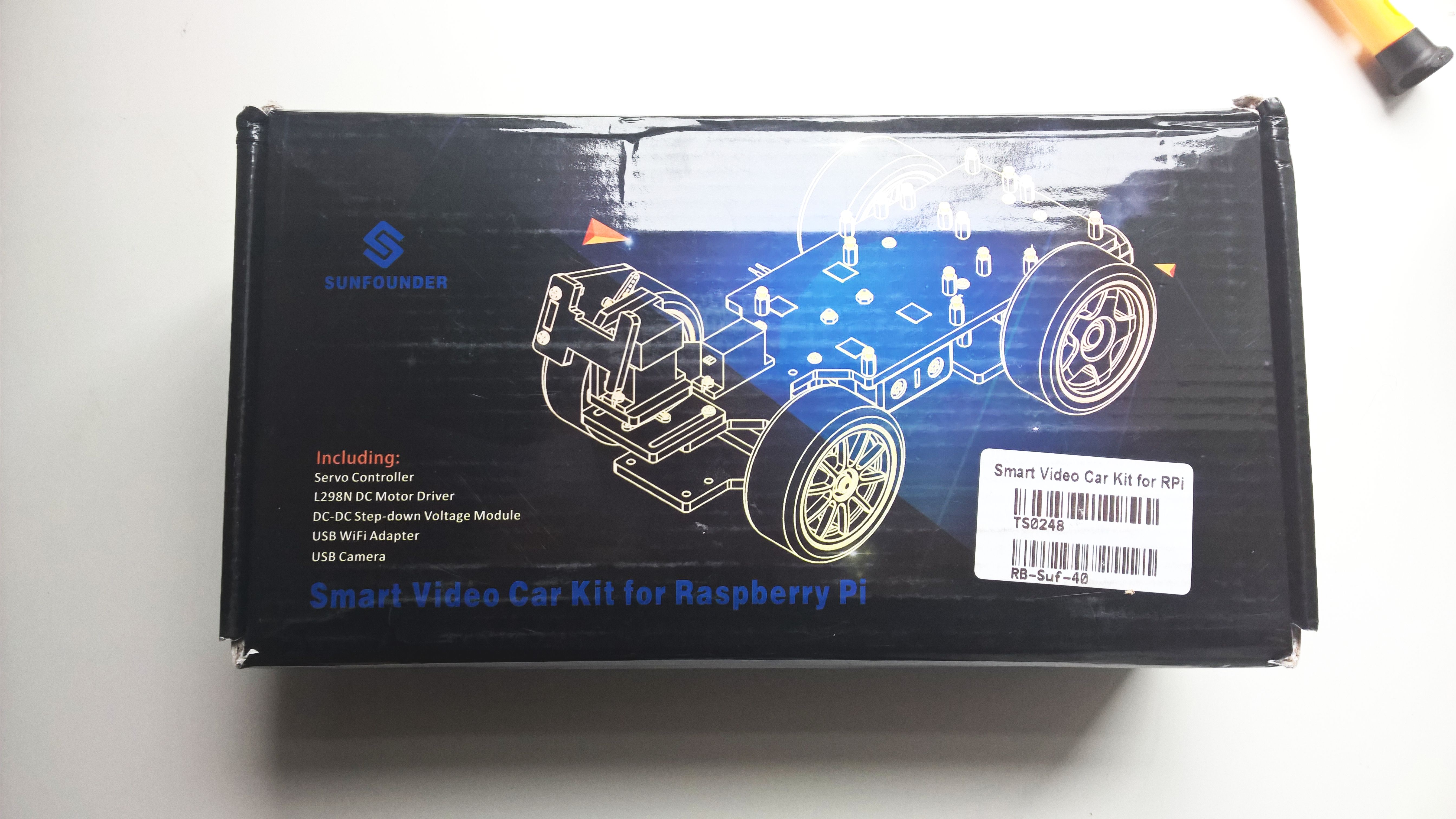
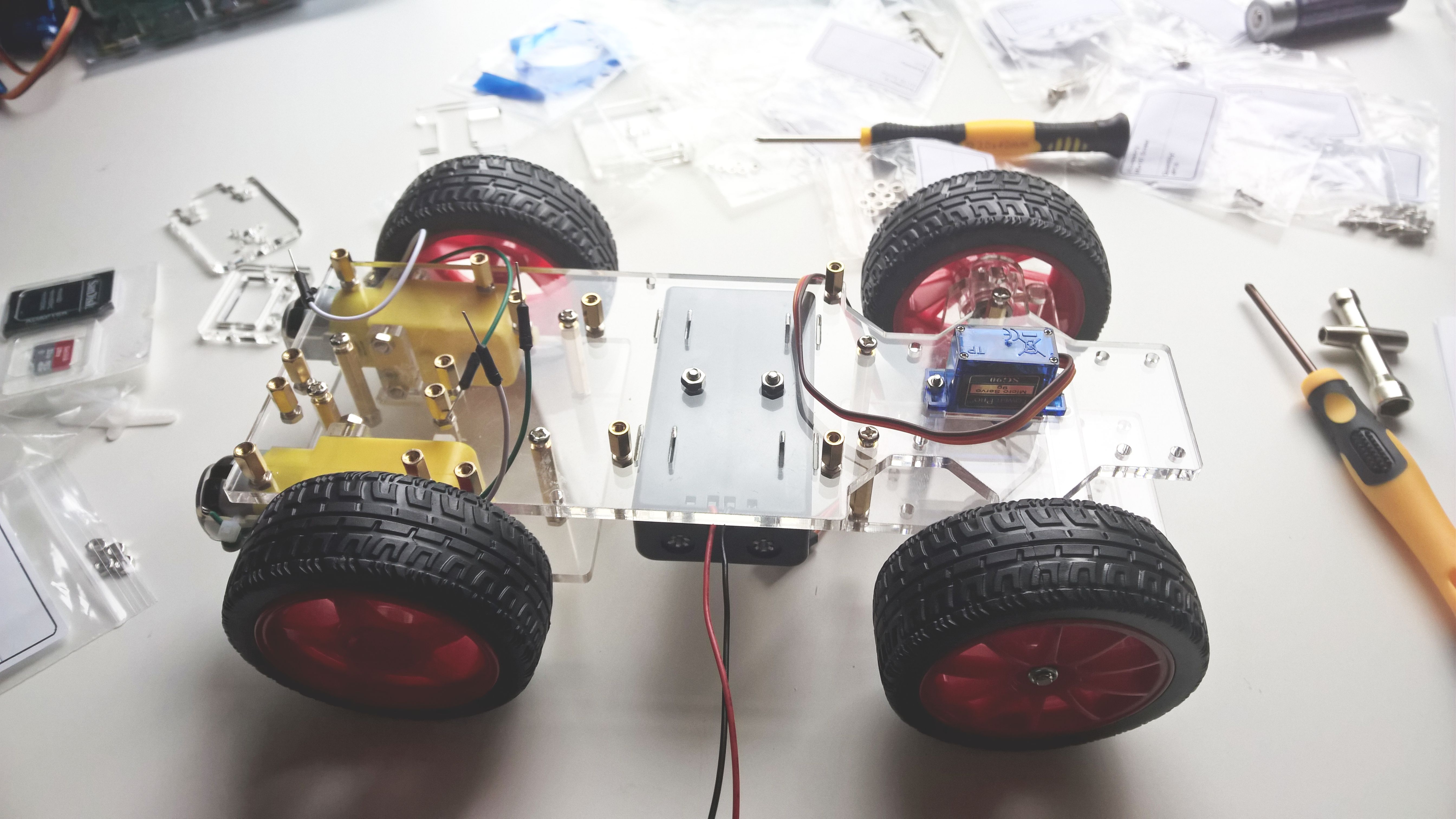
This post is going to illustrate some of the steps involved in building a Raspberry Pi car robot kit, namely the Sunfounder Smart Video Car for Raspberry Pi. If you have one of these yourself, you've probably discovered that the box comes with its own detailed assembly and wiring guide in the form of a booklet. While the guide is useful and comprehensive, assembling a few of these robots has taught me that there are some finer details it does not cover. Thus, I won't repeat what's in the guide, but rather I will give you some tips and tricks I found useful.
Let's start with a look inside the box. The kit contains a fair number of components, but they are individually packaged, making searching for parts easy. This is especially true of the numerous screws and nuts, where each type comes in its own separately labelled resealable bag.
What's in the box. Batteries on the right are not included. Not pictured: USB to miniUSB charging cable and screwdriver (which I had accidentally left in the box!)
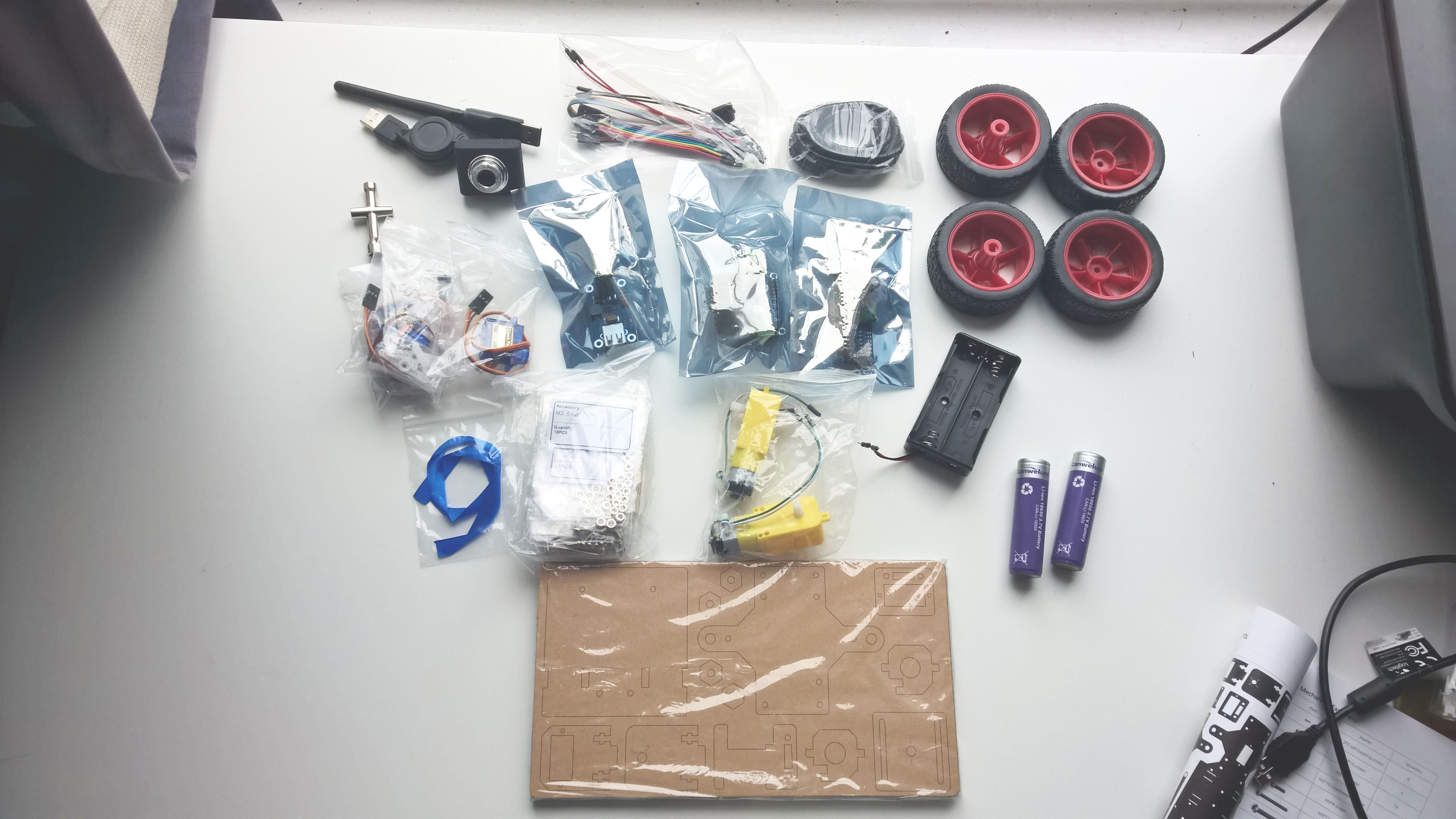
The chassis of the car is made of acrylic plates (the brown rectangle in the picture above), which are conveniently pre-cut. The brown look is due to a paper film present on the acrylic, which at first looks like it's part of the plate, but is actually very easy to remove if you scrape a bit of it from the corners and then peel off.
Next come the extra bits you'll need to buy if for the car to eventually become functional.
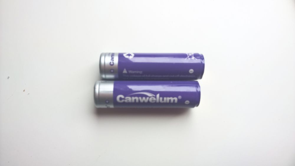
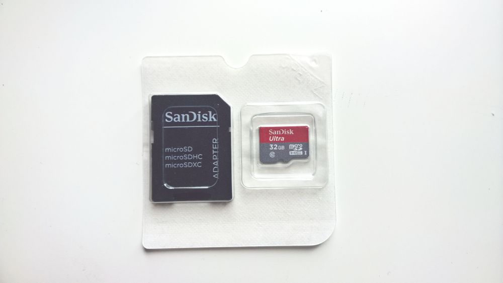
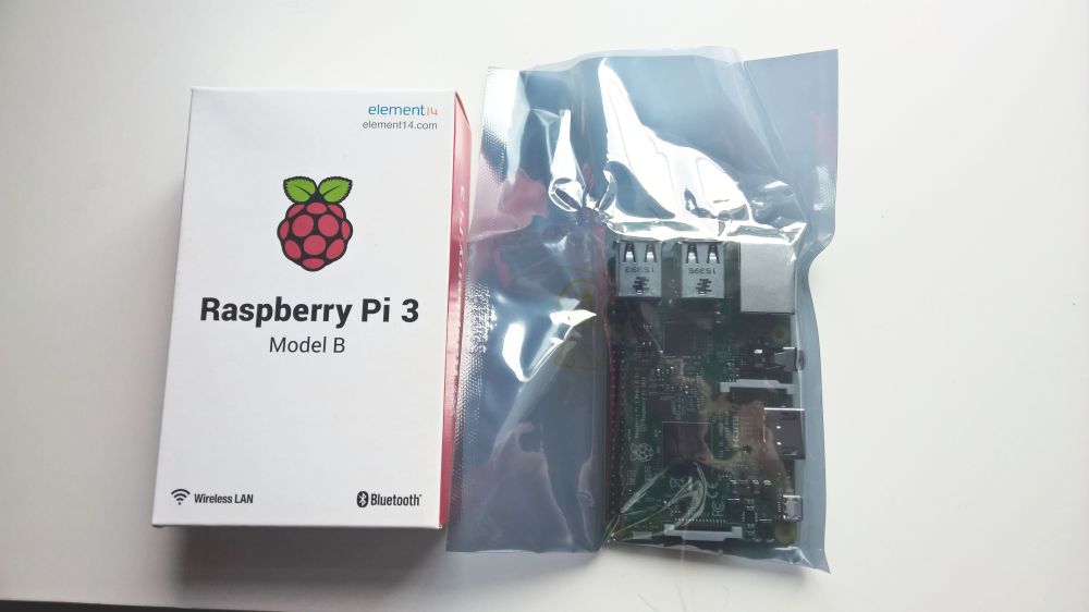
One very important thing to note is that while the kit comes with some basic electronic components (the servo, motor and converter boards in the three antistatic bags above), it does not include the Raspberry Pi, which you will have to purchase separately. The Pi, in turn, will require an SD card with at least 8 GB of storage to run. Lastly, to power all of the components, you'll also have to get a set of 18650 rechargeable batteries.
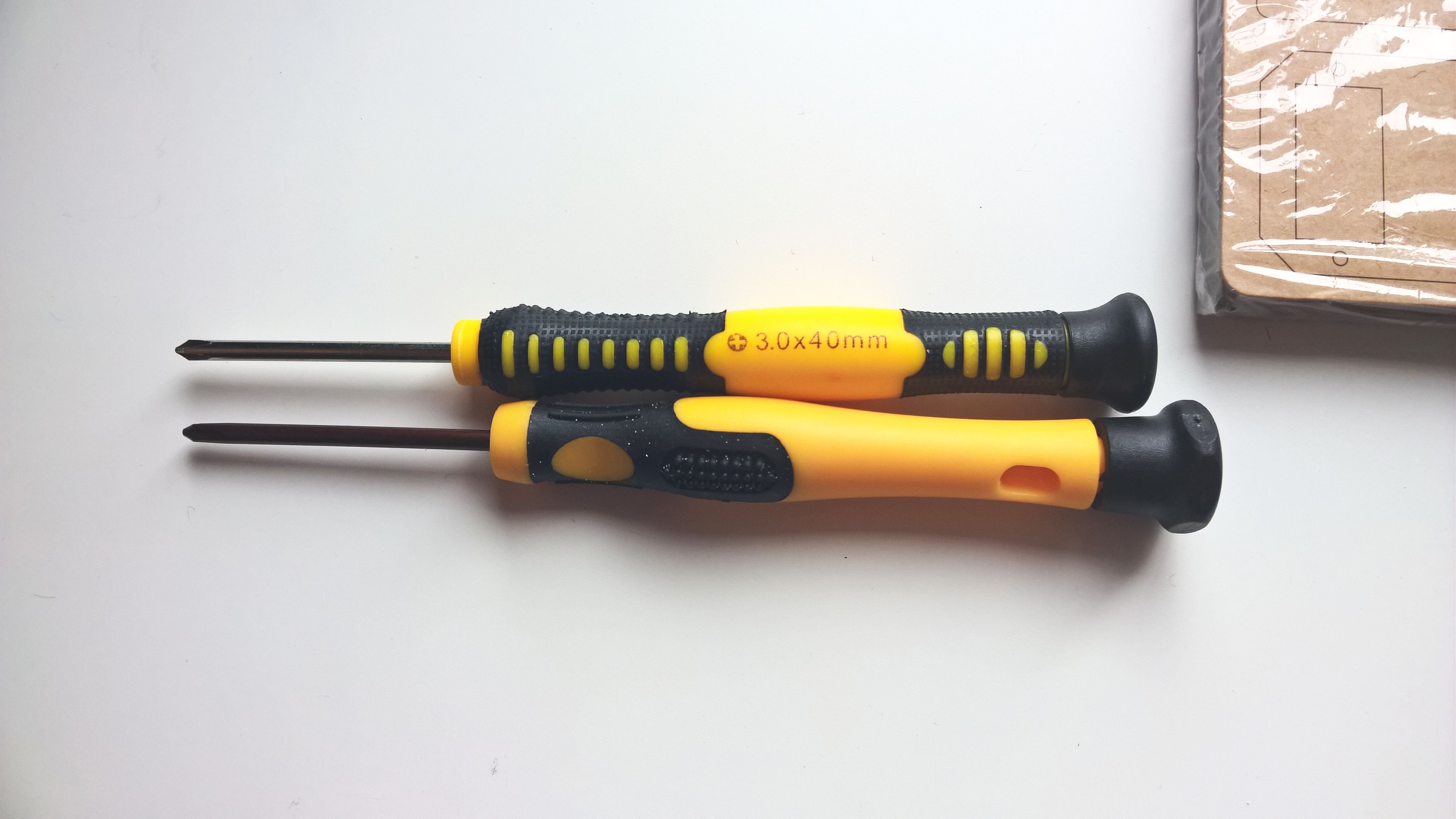
Before starting the mechanical assembly, take note of which type of screwdriver you got in the box. A few of the boxes we got had Phillips screwdrivers with dark-copper blades, while others had silver-coloured blades. This isn't just an aesthetics issue, though, since it appears the copper ones are a tiny bit larger than the silver ones and thus - in our experience - make the tightening of some of the tinier screws almost impossible. If you were not lucky to get a silver-bladed screwdriver with your kit, I suggest keeping a set of precision screwdrivers on hand, for the small and/or recessed screws.
Different screwdrivers. The 3.0x40mm one at the top is the silver-coloured one.
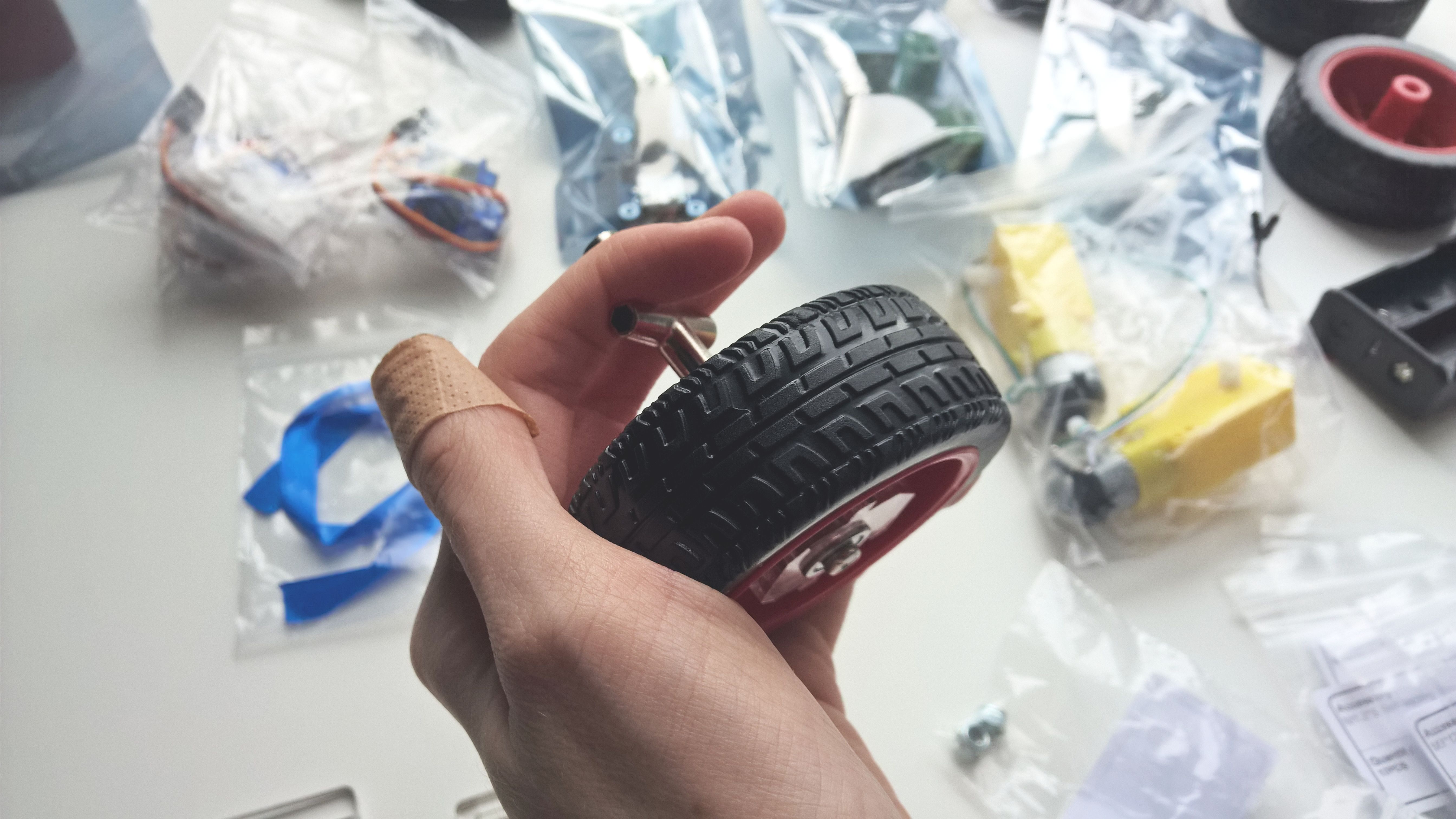
Now you can start assembling the car as instructed by the booklet, starting with the wheels. The setup here is pretty straightforward, so I'll just leave one tip on how to best tighten the self-locking nuts on the steering (front) wheels. I found it useful to hold the nut in place with the nut driver and then drive the screw in from the other side. In terms of tightness, as the guide says, you'll want to make sure the screw doesn't slide around, but also doesn't prevent the "spiked" acrylic plate from rotating freely.
Holding the M4 self-locking nut like this makes it easy to get a snug fit around the screw.
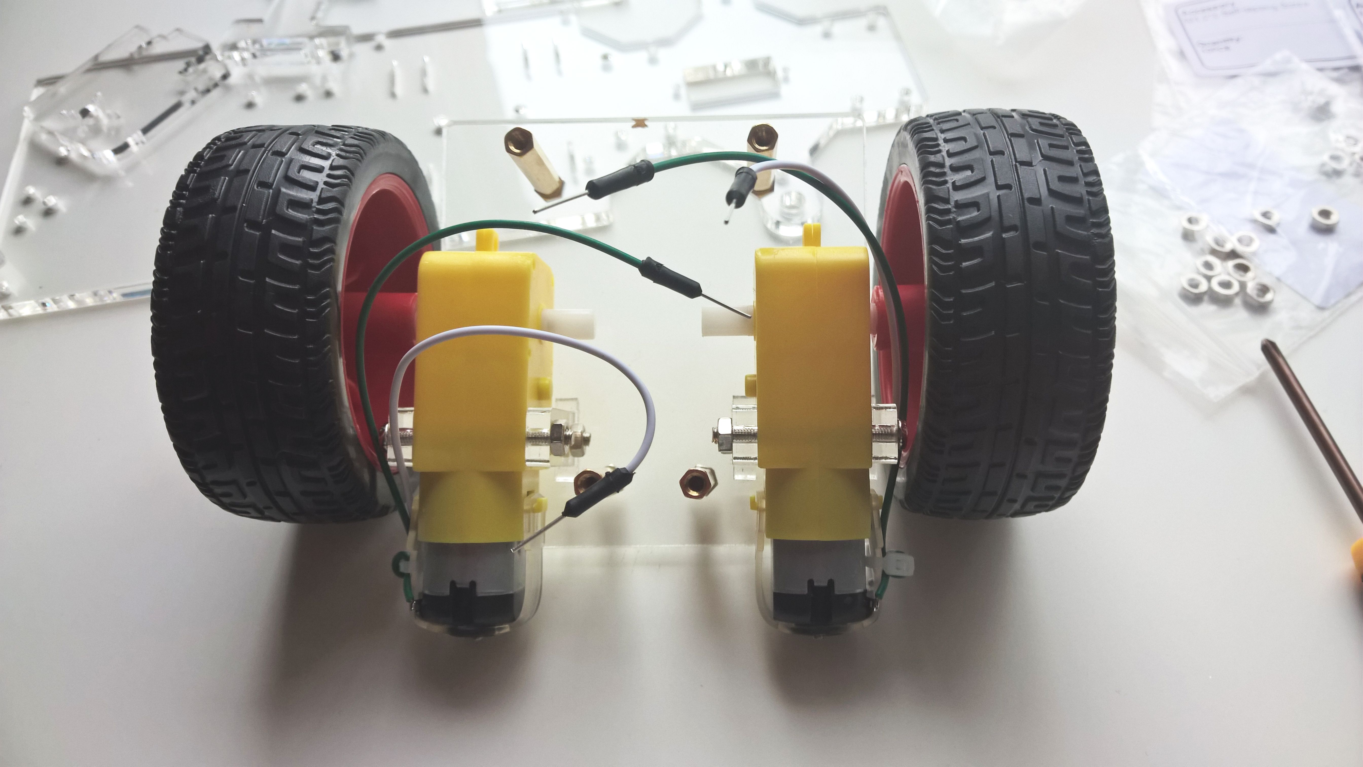
Continue with the driving (back) wheel assembly, to get this unit (view from the back of the driving wheel unit. Note the orientation of the motors with respect to the back of the car.):
Next, adjust the servos as instructed. I have generally found that two of the three servos make a distinctly different sound when the gears are turned. Thus, I deemed that those two had to be the camera pan/tilt servos, while the odd one out was the steering servo. I don't have any official documentation on which to base this tip, though, and I'm also pretty certain that any permutation of servos will function just fine, but it's something to note nevertheless.
Now put together the rocker arm, steering linkage and upper plate and then bring together the front chassis, upper plate and back chassis to form the complete main car body (chassis assembled):
I've generally found that screwing in the battery holder with the jump wires on the right side of the car is best, as it puts the wires closer to their connection point, which will come later.
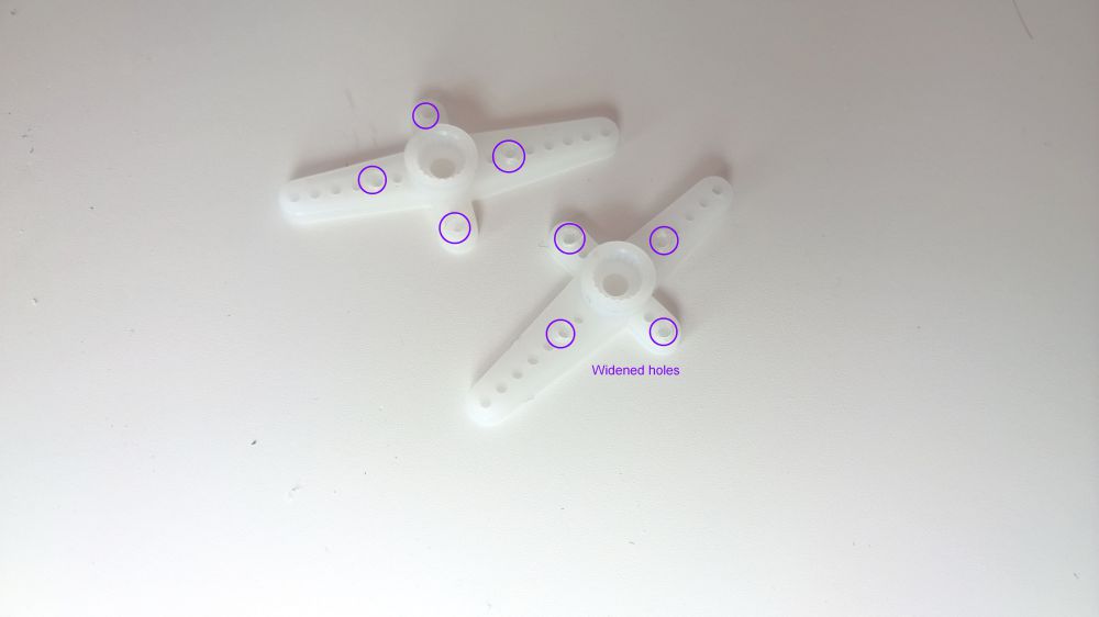
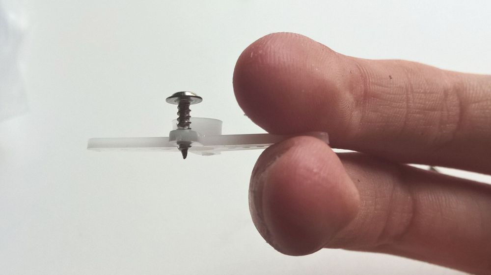
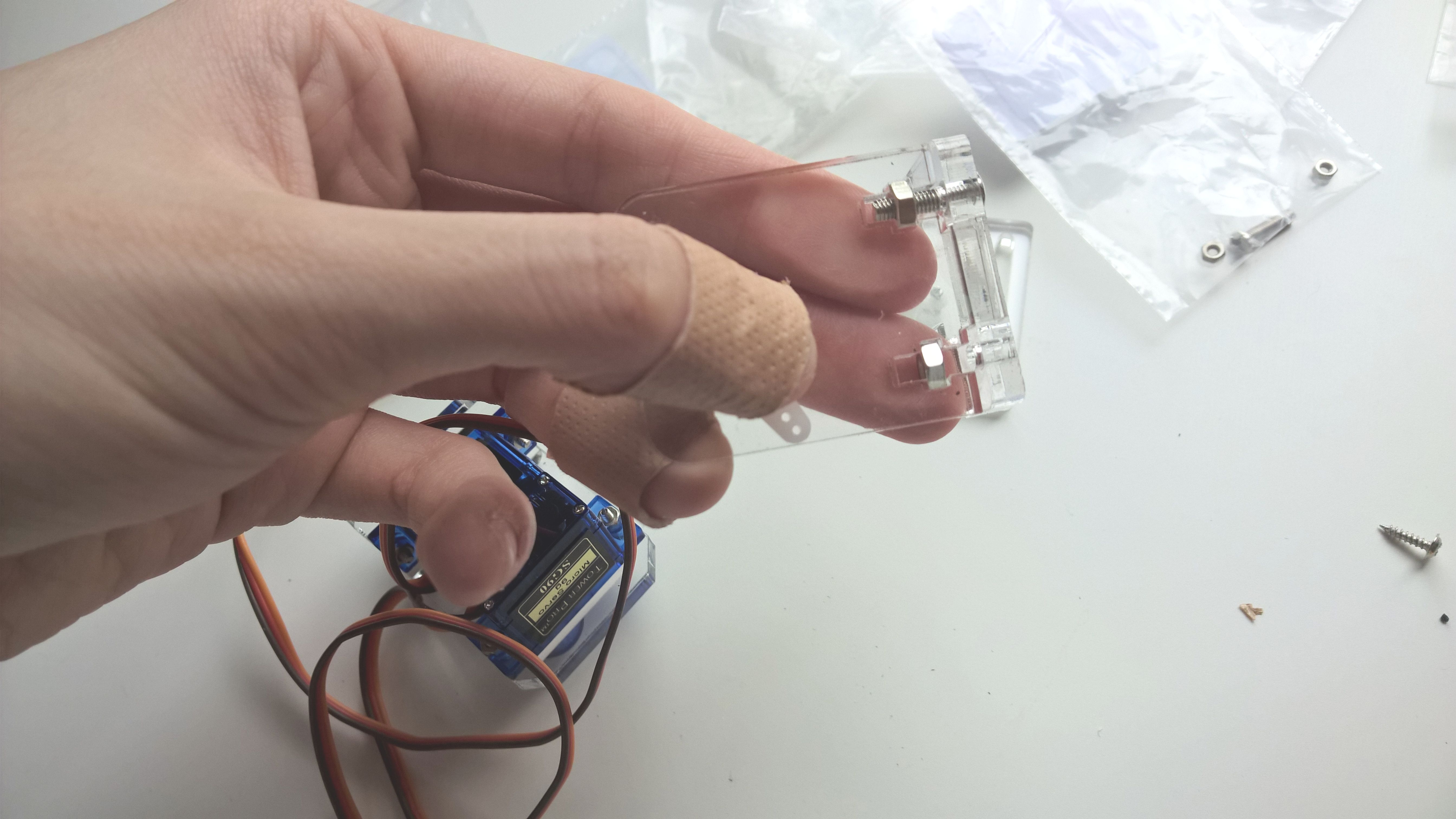
Next up is the construction of the camera pan and tilt unit. This part is tricky mostly for its use of the self-tapping M1.25 screws. These are very tiny and it is difficult to apply enough driving torque to them so that they tap both the plastic rocker arms and the acrylic holes below. Thus, to make the screwing task easier, use a M28 self-tapping screw included with each servo package to widen the holes on each rocker arm and the corresponding acrylic plate holes, as shown below:
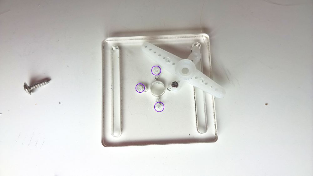
Now the M1.2*5 screws should go in far more easily, but still securely hold the plastic rocker arms in place.
The servo assembly is a simple task, as is the right angle attachment of the support plates. The only potentially tricky bit is getting the M3 nuts to sit in their intended spot in the acrylic plate before screwing in the M3*12 screws. Nuts go in first and then the screw is tightened within them.
Finish up the pan-tilt unit and attach it to the chassis and with this last step the mechanical assembly of the robot car is complete!
Now secure the electronic components to the main acrylic plate. Each circuit board is attached with four screws and you may want to ensure the screw holes are properly aligned by attaching the first two screws diagonally, as shown.
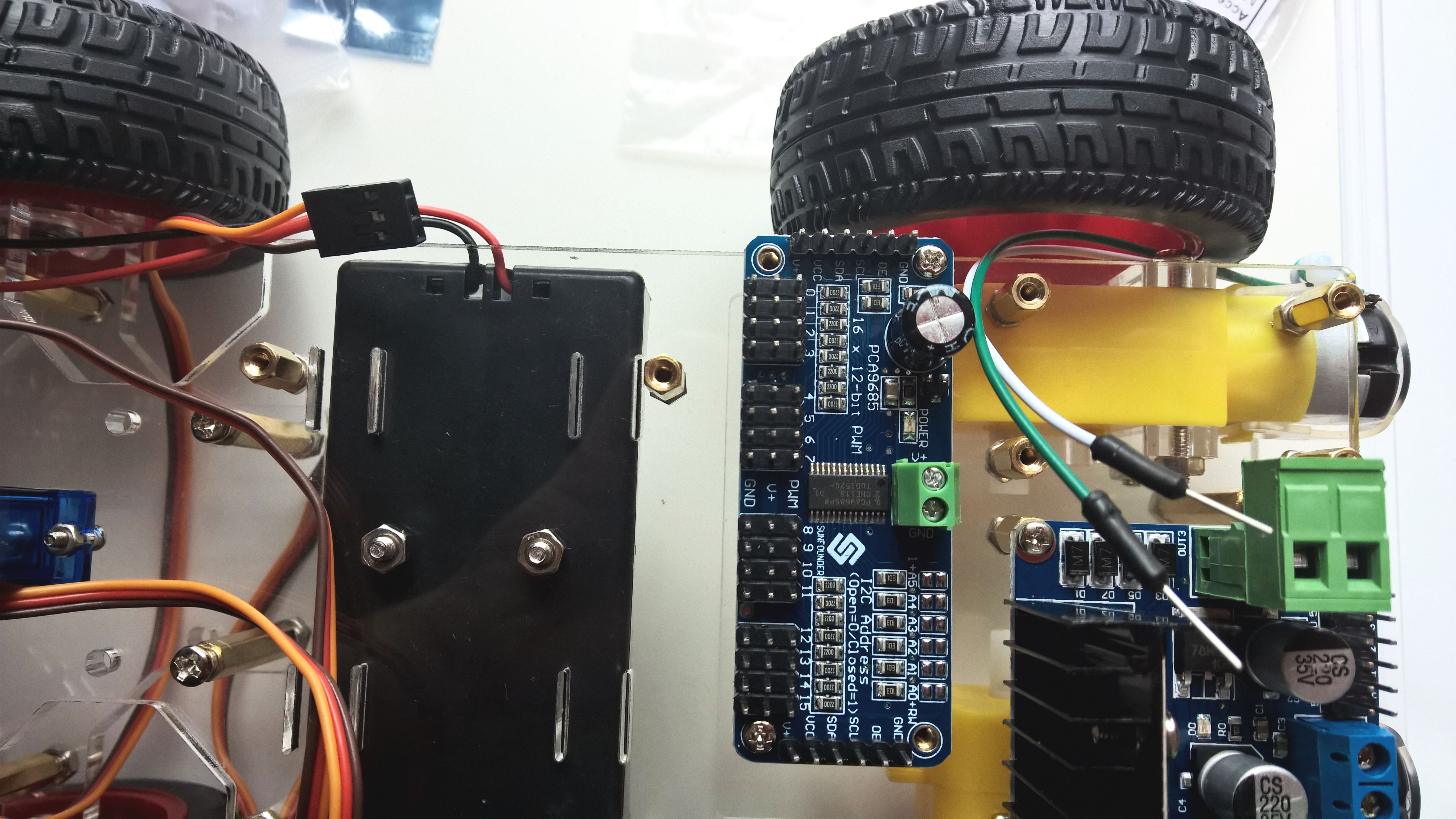
A diagonal placement of the first two screws makes sure the other two will go in easily. Take note of the orientation of the servo controller (with the green connector unit facing the back of the car).
If your Raspberry Pi's SD card is fresh out the box and unconfigured, it's probably best if you skip on screwing the Pi onto the chassis at this stage, as doing so will make the HDMI port inaccessible. It is of course possible to configure the Pi while it's "headless" (using a direct LAN connection), but having a monitor connected to the HDMI port makes the setup significantly easier. This particular car will have a fully configured SD card (cloned from Terra's card), so I will be screwing in the Pi as well.
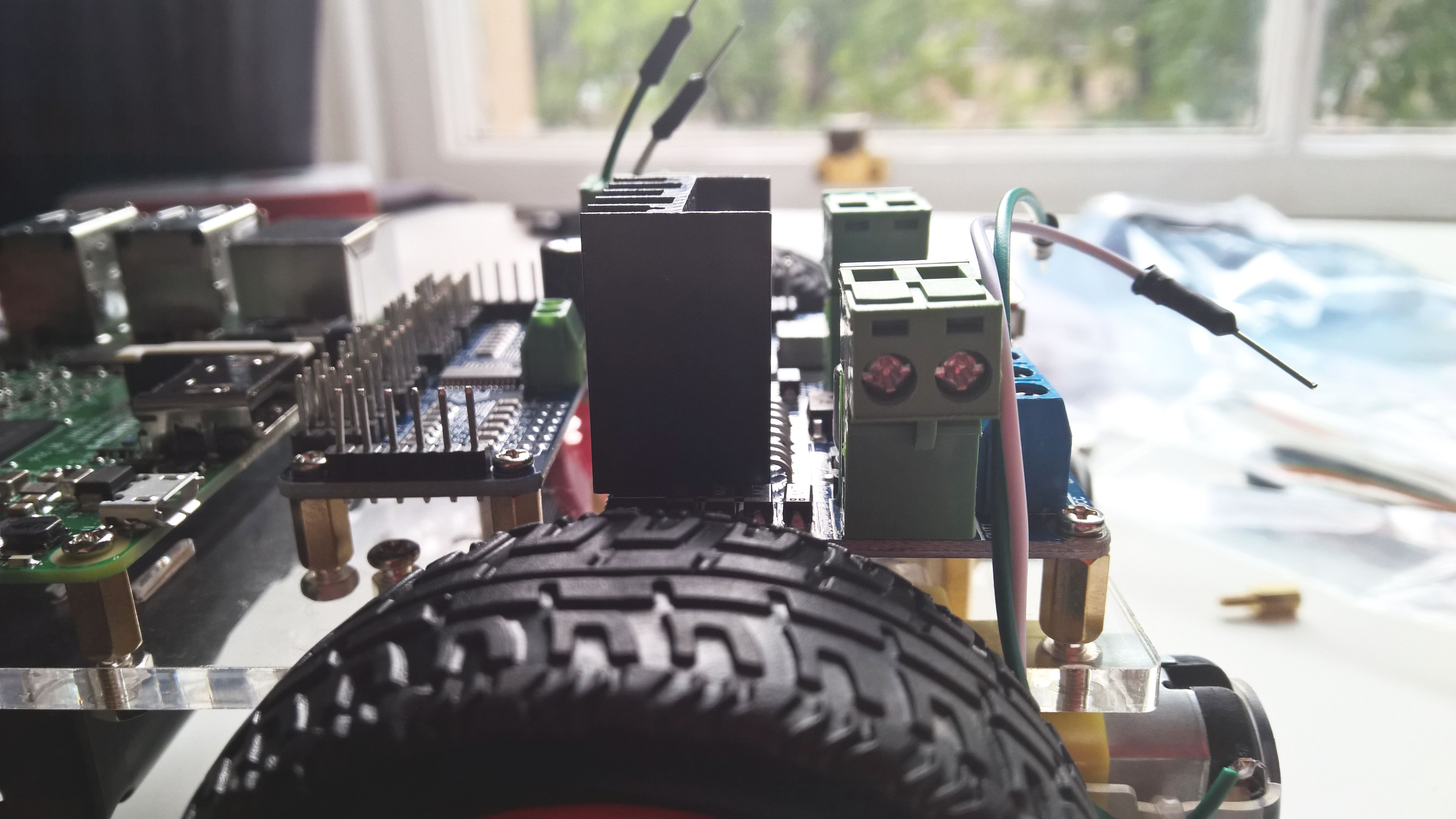
Before you start connecting any of the jump wires, loosen the screws in the green/blue connector jacks. The screws on the sides of the green connectors and the top of the blue connector at the back are there to hold the jump wires in place when tightened.
Now the wiring can proceed as pictured in the instruction booklet. Make sure to re-tighten the connector screws once the wires are in place. Finally, connect the camera and the microUSB charger to the Raspberry Pi. If your Pi is the same as the one pictured (Pi 3 Model B), it already features an in-built WiFi module, so the dongle provided by Sunfounder is unnecessary. For Pi 2s, you'll have to attach it in order to get a wireless network connection.
Pop in the batteries and your Sunfounder Video Car should power on. If your SD card has Raspbian (or another Pi-compatible OS) installed, you can go ahead and insert that into the Pi, along with some peripherals if needed for configuration.
And that concludes the building process! Here is Mercury in its fully-assembled glory:
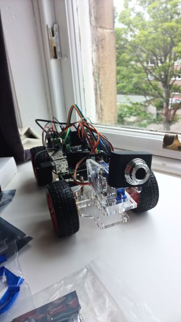
My next post will contain Part 2 of the setup process - installing and configuring Raspbian on the Pi and also getting ROS up and running.